Uh oh what did I get myself into 🤪
Just wanted to feel horse riding in Red Dead Redemption 2 game. #rdr2 #gaming #horseriding
I guess that counts as #simpit too https://tinandjar.com/2023/01/09/feel-game-gun-recoil/ 🤣
Hell of a #DIY #controller. Also no idea how that monitor survives this onslaught.
Jon cobbles up that chat "AI" to his #EliteDangerous #SimPit. Really fun stuff. My kind of nerd level 👌 including text to speech to make it a snippy bitching Betty: https://youtu.be/miQBHcP8YzA

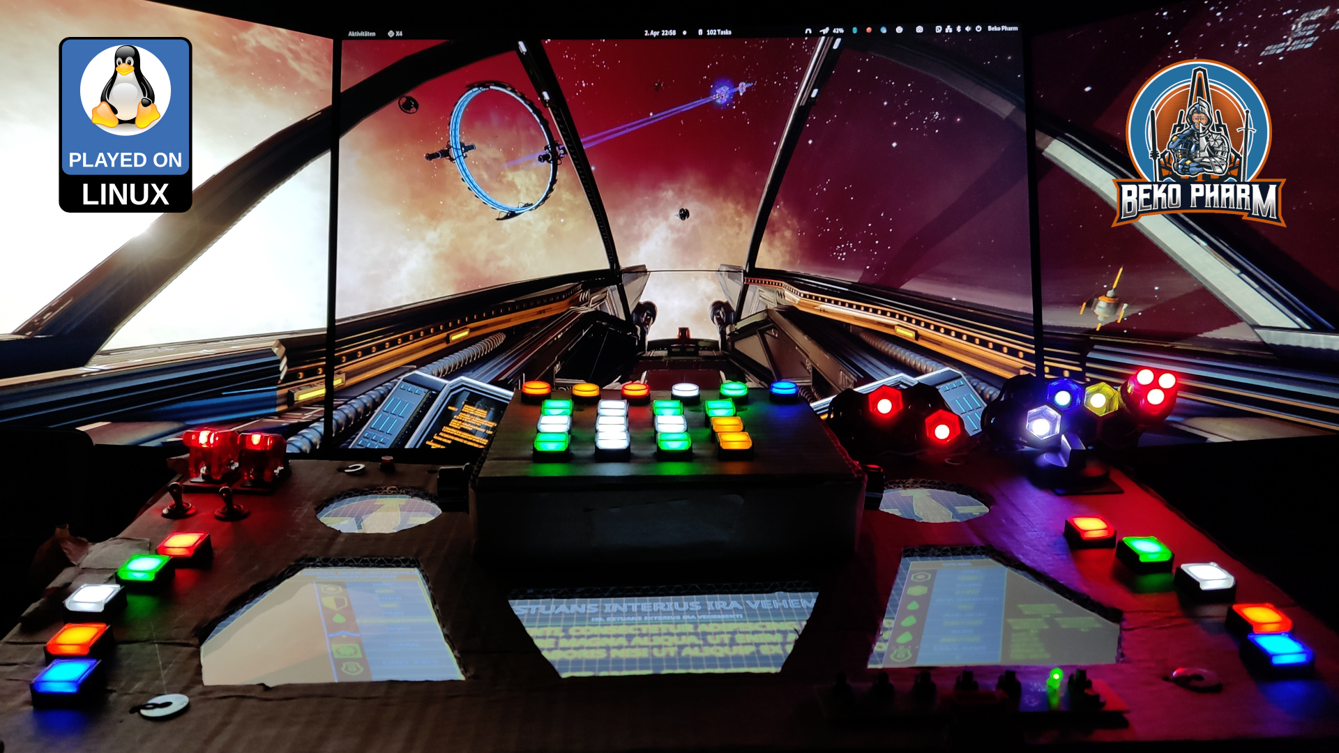
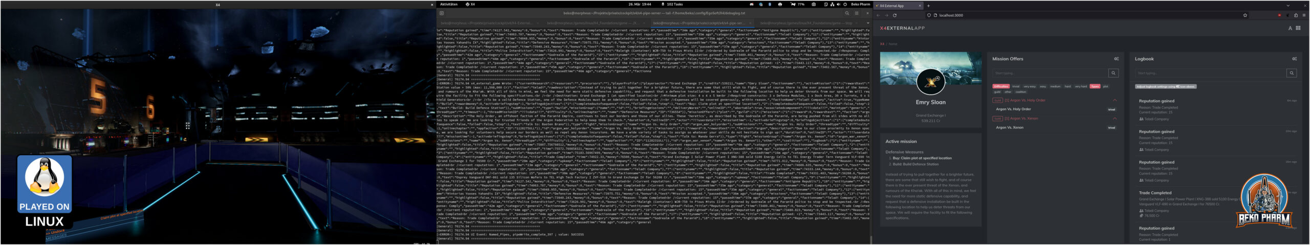
I hacked a mod for X4: Foundations to get ship telemetry and targeting data to my “Primary Buffer Panel” via a socket. This is a demonstration of my simulated cockpit made from cardboard on a budget usually used to play Elite Dangerous now also used for X4: Foundations. This is work in progress.
In use:
This is loosely based on the Python Pipe Server mod for X4 that is sadly Windows only using Named Pipes. I fixed that for Linux PC by side-loading the library LuaSocket and starting a socket server directly in X4. That’s right, the Python Server is simply not needed now and companion tools may directly connect to the socket. It’s a nice bonus that LuaSocket also allows a UDP or TCP server depending on how it is started. That was some piece of work though and I’m still wrapping things up to publish my code changes. I’m also still looking for testers so if you’re interested get in touch!

So you _still_ think you can’t space pew pew on Linux PC? Think again. I do it all the time: https://beko.famkos.net/2021/10/16/space-pew-pew-on-linux-pc/
Modding my X4: Foundations into using the same data format as Elite Dangerous does so I can run my SimPit without changes. Things are coming together nicely 😀

Here are the humble beginnings[1] of a working example to read the ship status of #x4foundations in a format very similar to the Status File of #EliteDangerous
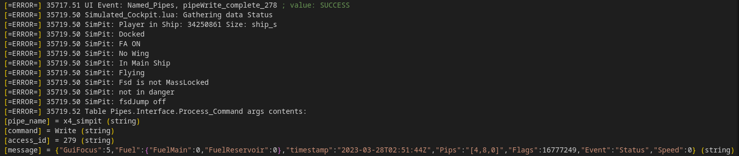
Both games are quite similar and by using a “well established” format it should be possible to use this with existing companion apps – like my own #SimPit
It uses the “Named Pipe API” of “sn_mod_support_apis” – on #Linux PC 😁 This was not supported by this MOD so far but I made it work.
Well, at least on my machine 🤓
And yes, the pipe server works with some minor adjustments for other _existing_ apps as well. Here is a demo of #X4ExternalApp with a data feed directly from X4: Foundations – it does not use the #X4PythonPipeServer though, since that is not really needed, so I had to make some small adjustments in it’s connection routine but that was like 2 lines of code 🤷
[1] TBF the humble beginnings were back in 2021 (https://beko.famkos.net/2021/05/01/getting-into-x4-foundations-modding-on-linux/) but I kinda let it slide to tinker and build my Primary Buffer Panel (https://beko.famkos.net/category/simpit/) first. Other games made it easier to retrieve game data and I did learn a lot during that time but it was X4 that started it all.

First time in the new computer room and in months that I run my #simPit. I really missed that 🤓
https://www.youtube.com/watch?v=8anoiEABXbM Jon built a smoke machine into his #simPit and explains how not to do this at home and why this is a bad (albeit fun) idea 🤓😂
My #simPit was featured on Down To Earth Astronomy and that made me really happy 😊
A lot happened since my last update on the simpit – under it’s hood. Function wise it changed not so much so the older demonstration video is still better for a quick demo. I still assembled a new video from clips of the first evening with the new hardware:
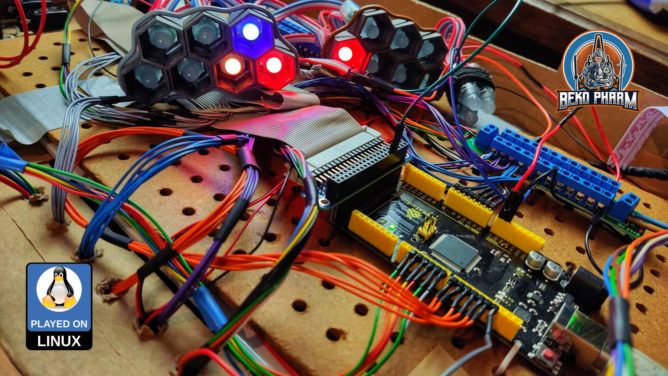
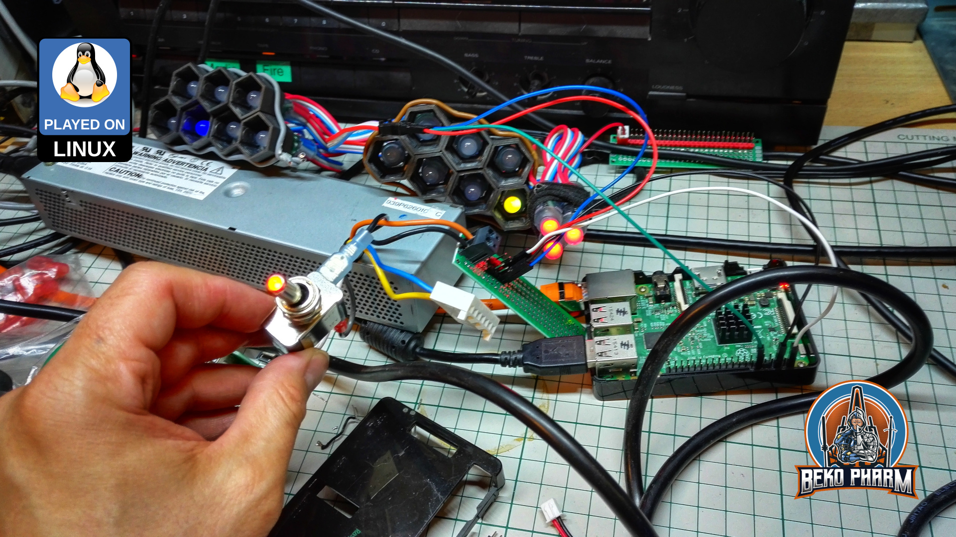
So what changed? I got rid of the CY-822A USB joystick controller that, while good, was also limiting. Especially in inputs and how they would react. The Raspberry Pi, that I used to drive the status indicators, is also gone. This is all replaced by one single Arduino Mega that is connected via serial over USB.
A custom joystick daemon written in Rust is listening for data from the #Arduino and feeds back the flags of Elite Dangerous to drive the blinken lights. I also extended the source to add me some rotary encoders (with push button function) and I’m very happy with the result of this. That makes a whopping amount of 48 buttons and 6 axis (where 2 axis make one hat). And it feels _so good_ to have e.g. self destruct or eject cargo save under a protective cover now 😀


The panel also got an external PSU with enough ampere to drive as many LED as I may imagine so I no longer abuse a phone charger for that or risk frying of the PCB / USB.
With all that in place I streamlined my pre-flight check-list quite a lot because way less hardware is involved and most of this is automated by now. It wasn’t all fun n giggles tho and while the new hard- and software “just worked” in e.g. #StarCitizen it was #EliteDangerous that gave me a hard time to actually use most of the new buttons.
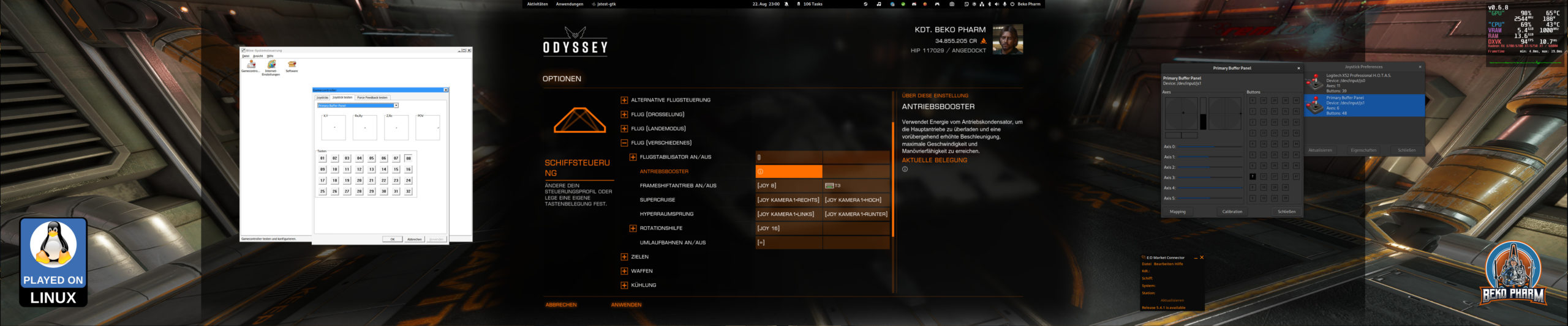
Turns out it had no idea about the device and model identifiers reported by the joystick daemon and that the kernel assumed a gamepad based on declaring e.g. ButtonNorth via the more recent xinput system really didn’t help – because that limited the amount of read buttons via xinput severe! In the end I set it’s identifier to a “vJoy” device. That I found in the DeviceMappings.xml of Elite and since this could be basically anything I gave it a try (and removed all “offending” magic gamepad buttons from the code) and sure enough Elite started accepting the inputs as expected and from there it was smooth sailing – got even the hat working.
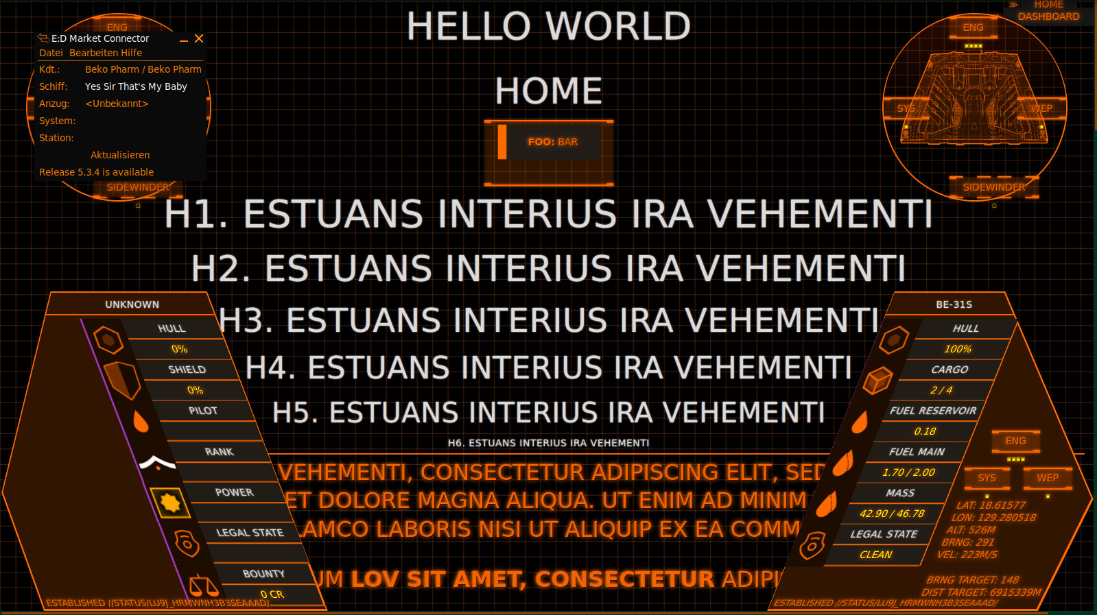
Oh and for everyone who is wondering what exactly they are seeing on the “MFD” when I’m playing Elite: That’s basically a Website using the #Arwes FUI framework. Find a quick demo video here. Without the cardboard covering up parts of the screen it looks basically like this:

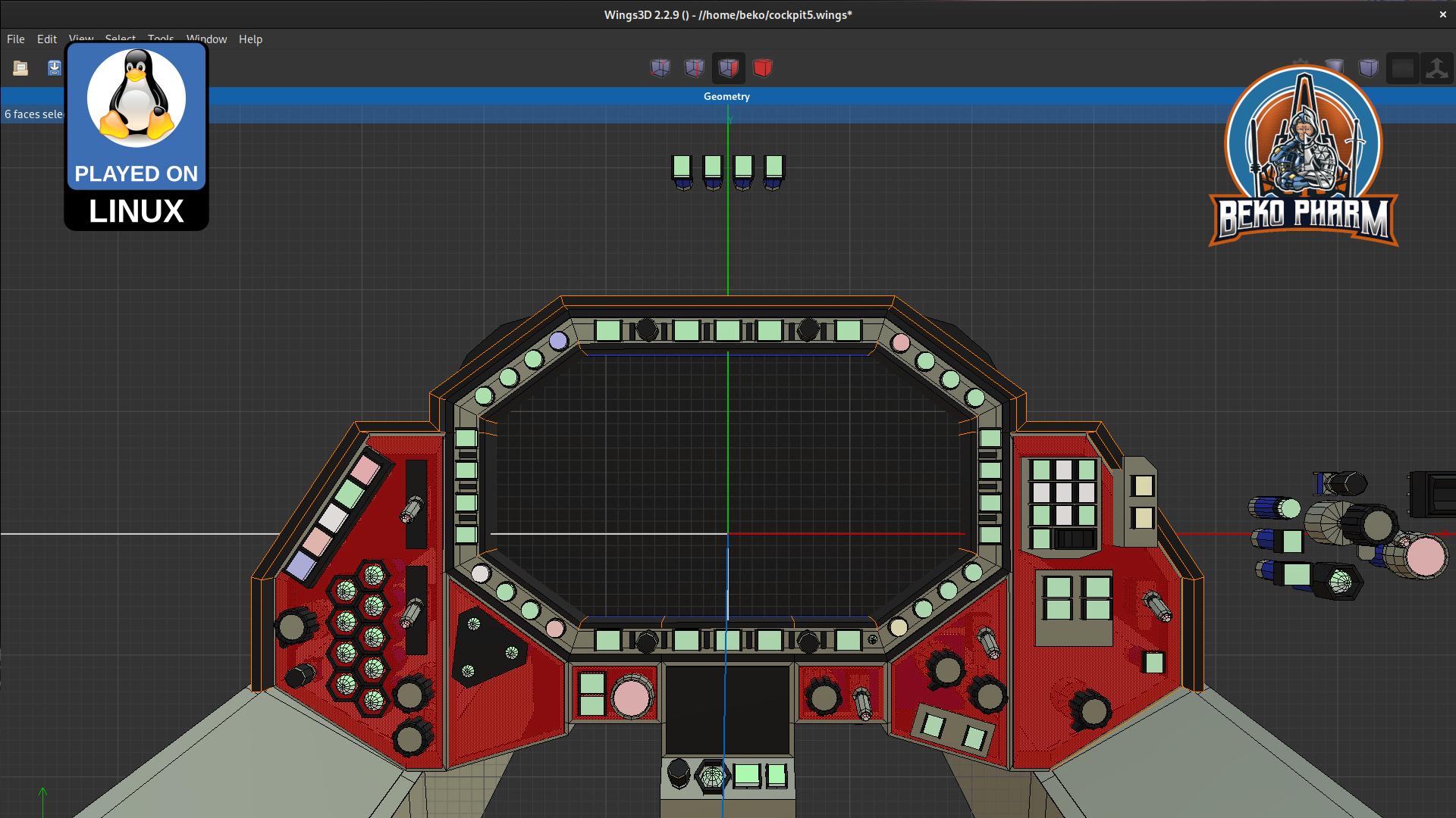
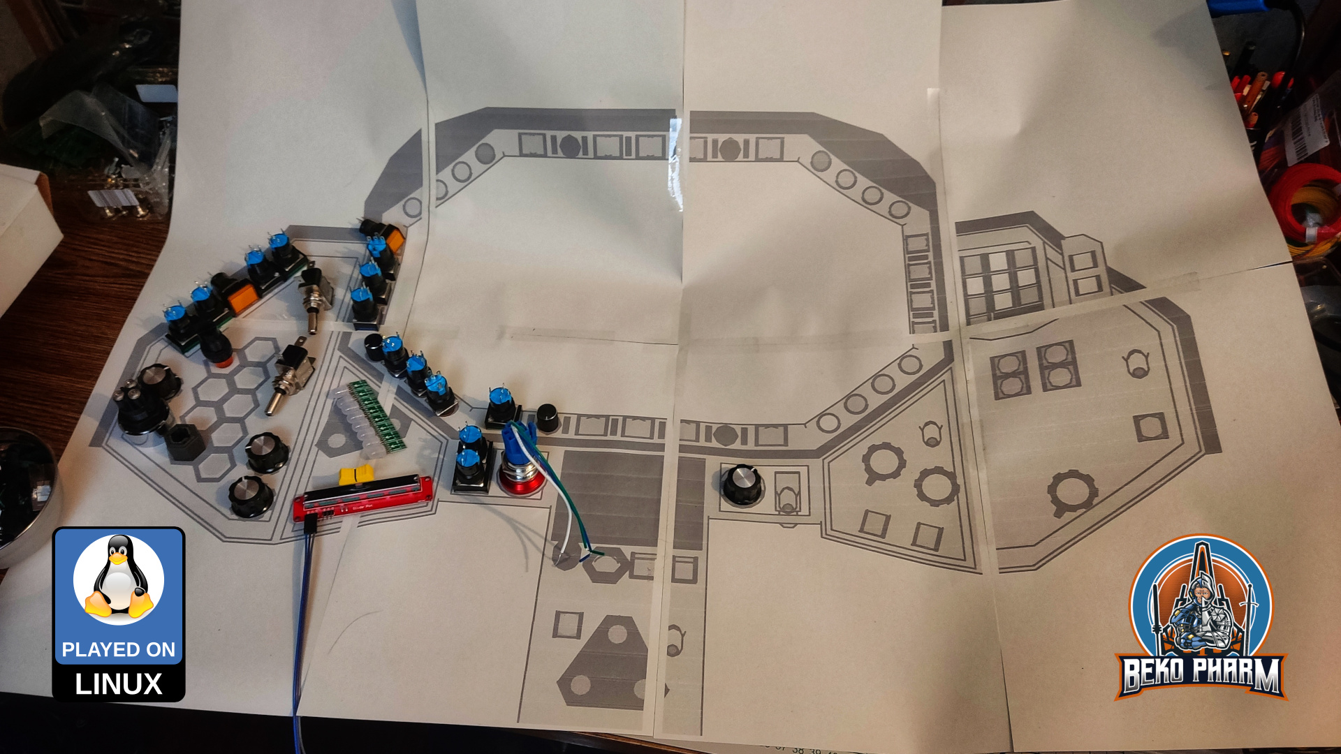
I also started doodles for a version 2 – now that I have an idea what I really want.