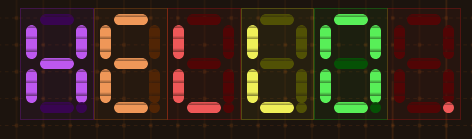
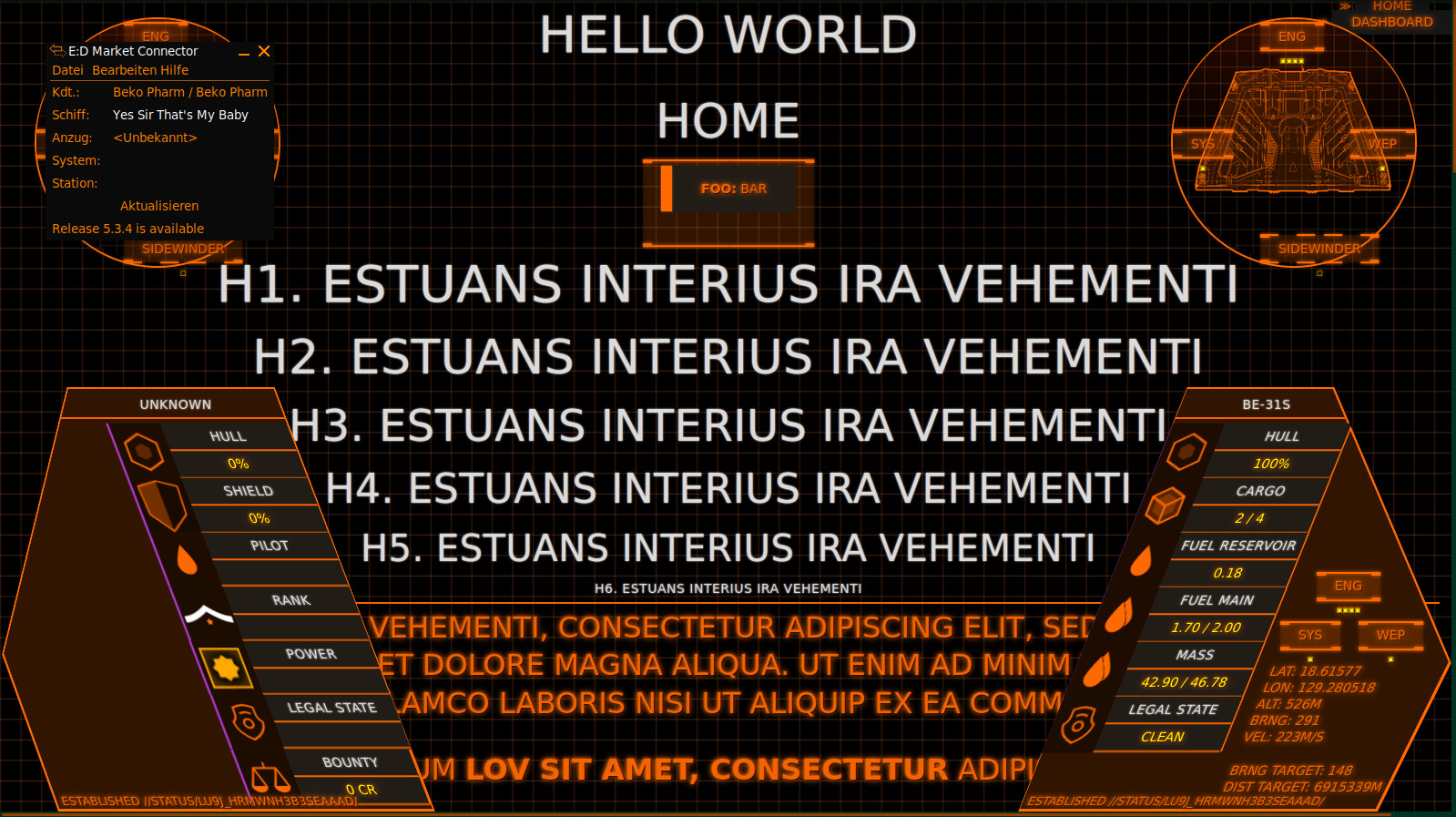
The segment displays are heavily inspired by #AugmentedUI project (https://augmented-ui.com/) where I’ll borrow some more elements. Learned the neat fake scan lines from there too. And yes the 8 segment display works by shifting bits under the hood 🤓 This isn’t really needed for an app but I have plans to add some real segment displays eventually (I do have a whole box full with these!) so I wanted to know how to implement this anyway.
Video from an earlier stage in the development demos the scan line effect.
The bars are configured with parameters in size, count, percent, colours and thresholds 😁 I also added a random chance of 5% to shift the hue a little bit because just as in real life nothing is perfect.
And yes they are fully themed so switching the colour theme also affects the virtual VFDs.
I’m also going to replace the older horizontal bars, that look way too boring in comparison.
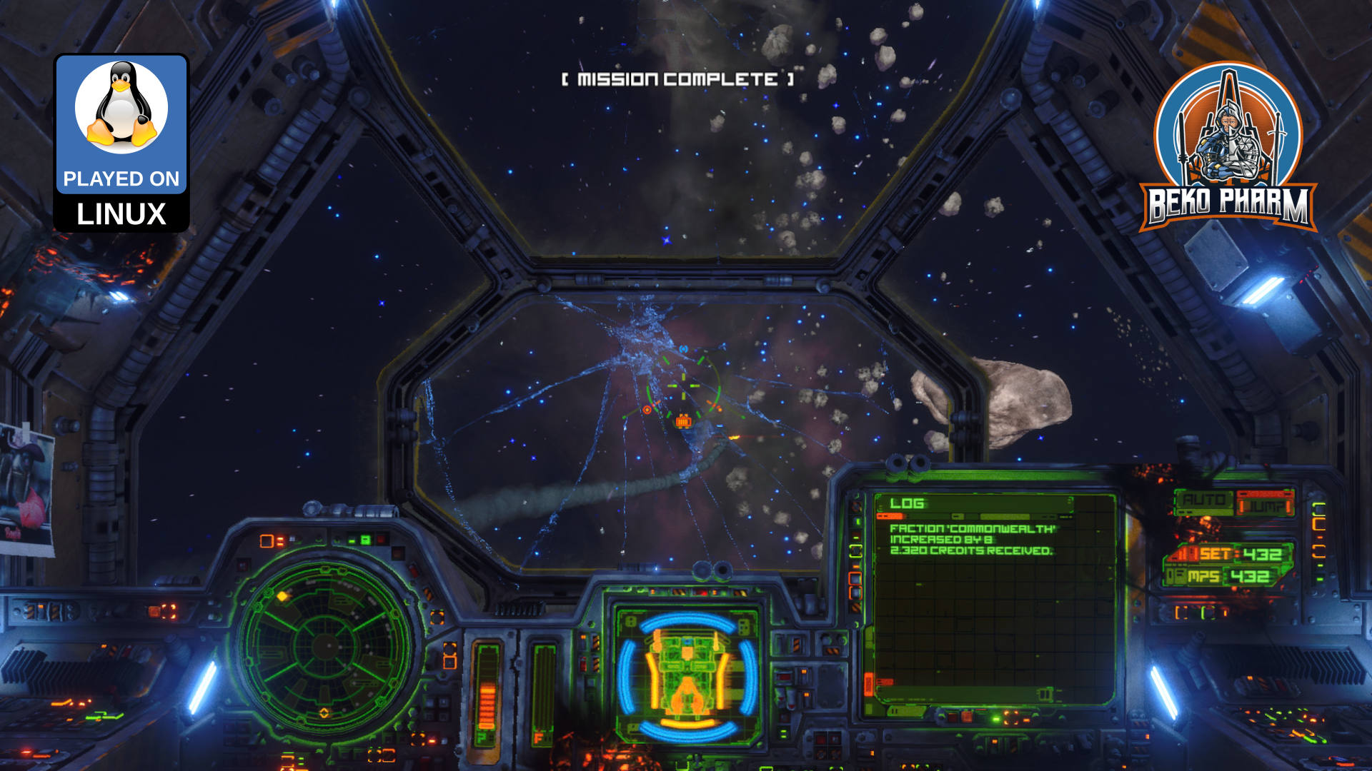
This uses my X4-SimPit extension for X4: Foundations, that sends ship telemetry via a socket to my node-red plumbing pipeline, which in turn forwards data to Websockets, SocketIO and MQTT. Various subscriber listen on the new messages to run blinken lights and my HUD app. I’m using the well known message format also used by Elite Dangerous so it’s compatible with that game as well.
X4-SimPit code (pending changes) is here: https://github.com/bekopharm/x4-simpit The cockpit panel has a dedicated project page here: https://simpit.dev/
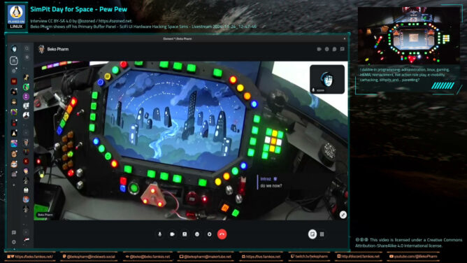
`@ozoned` interviewed me on my home cockpit on a live stream via his #Owncast instance at https://stream.ozoned.net/. This is a more condensed version of the stream that is still just 1h shy. We’re going over almost every feature of my Primary Buffer Panel and I explain how everything works. I also decided to add various photos, slideshows or video snippets during the talk only sections so things don’t get too boring. Sometimes that even complements the talks 😄
Ever wondered how to start your own DIY #homeCockpit / #SimPit on? It’s easy. Just watch this stream 🤓
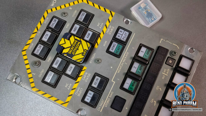
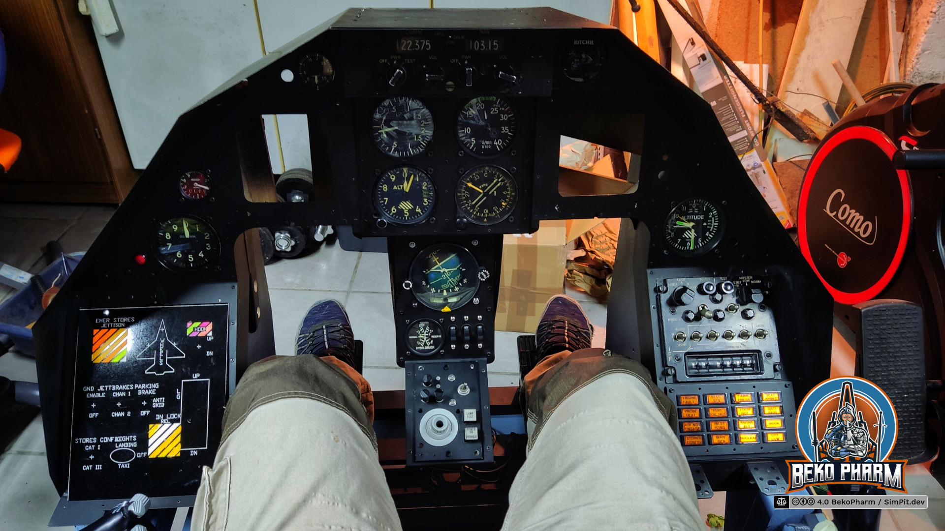
So I started taking a closer look at the various panels I got with the old #ViperPit, which is a challenge in itself, since not everything has a handy badge telling me what it is. It’s also not like I’d have a clue in the first place. Figured out that this one apparently belonged into a #Panavia#Tornado but I don’t know the exact model yet. It was installed in the rear cockpit on the left side of the front panel and operated by the Weapon Systems Officer and is apparently no longer in use since ~1990. It’s safe to assume that this thing did see action and was closer to space than anything else I own.
Side view of the buttons array
Next was finding out how this thing is wired to see if I can convert it into a button box for PC gaming. The segment displays look pretty straight forward and I’ll definitely need some multiplexers to drive them but that has a low priority. The switches can easily be checked with a meter but thanks to @kranfahrer@mastodontech.de I was able to track down some wiring diagrams as well. Turns out these are not also very old but apparently rather pricey too? Someone mentioned an eBay offer for whopping 300 USD for a single button – which is insane to me 🤯
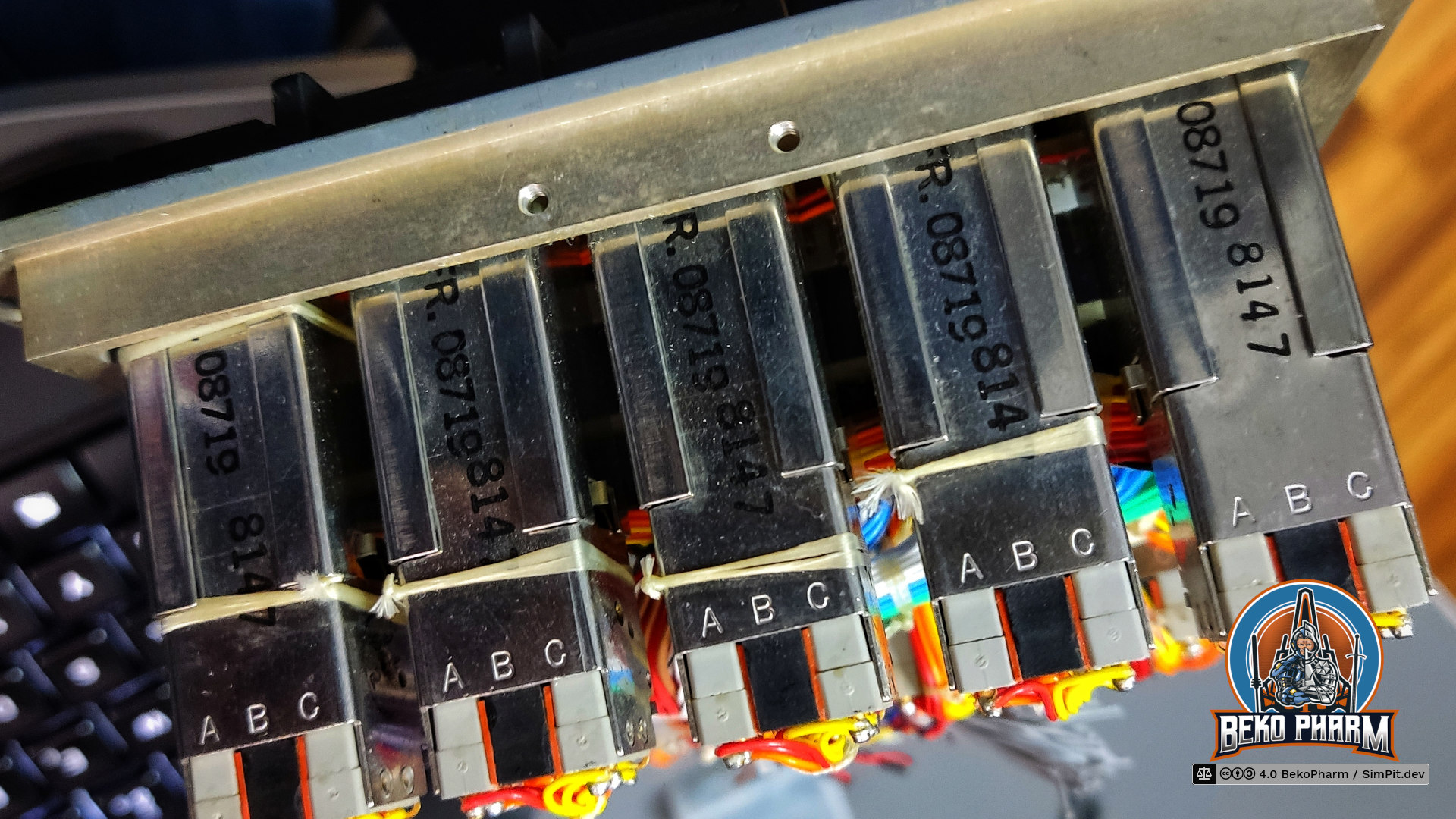
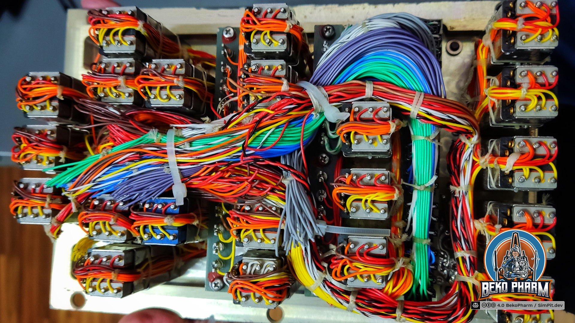
Backside of the Tornado WCP showing beautiful cable lacing.
Speaking of wiring: The backplate may be missing but some of the original cable management is still in place. This is where we can see the rather beautiful cable lacing, which is used in avionics for bundling together wires with waxed nylon or linen cord in an environment with lots of shaking and vibrations. No I didn’t know this before and would probably have ignored it but A Hornet’s Nest just released a video about Cockpit Cable Management where he talks in detail about this technique. Great channel!
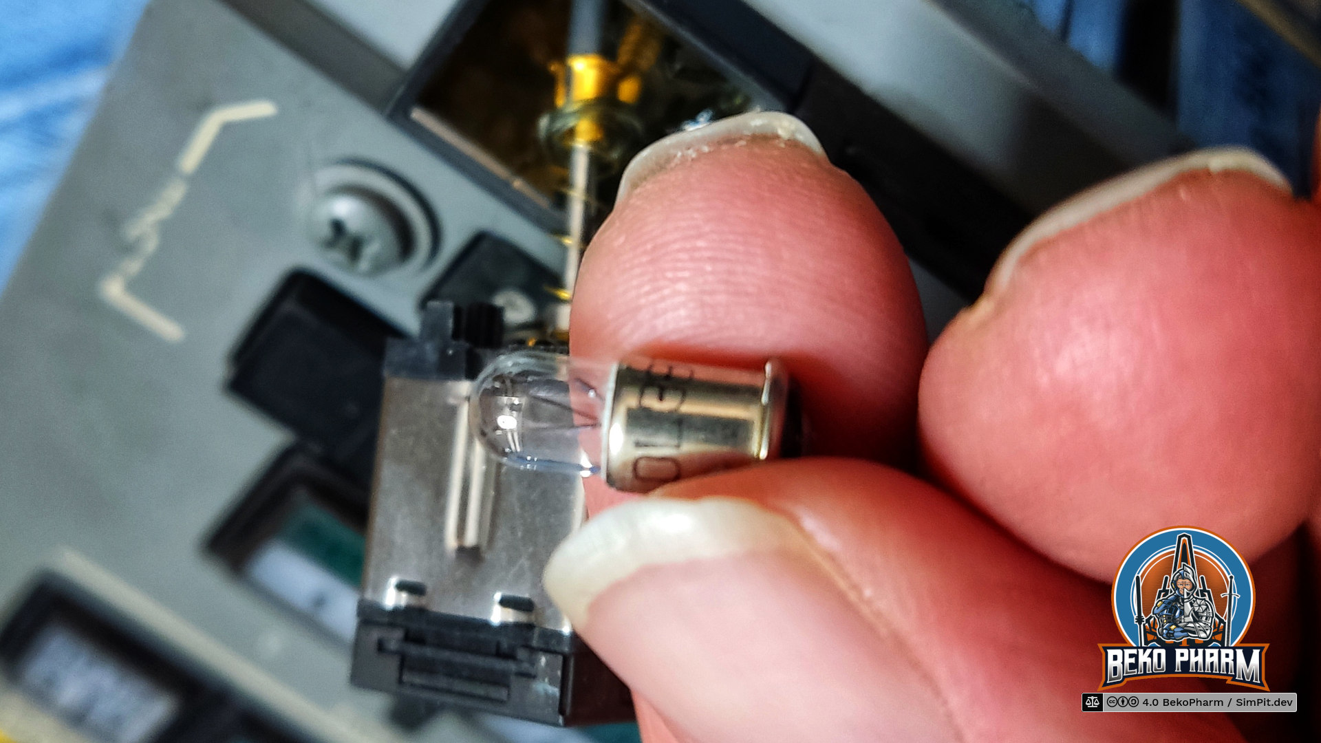
The lamp used in one of the buttons is not even LED yet
Another question was for what voltage the lamps are designed for. Each button comes with at least one lamp. This is a rather old fashioned and not a LED yet (and in fact LED replacements are rather expensive even). This specific one is the model OL387 rated for 28V DC and 40mA. Apparently this all is up to military spec MIL-S-22885 and bright enough to still be readable in sunlight and comes with high duty cycles before it needs replacements – so it will probably last a lifetime in my man cave 🤓
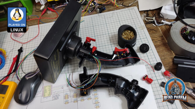
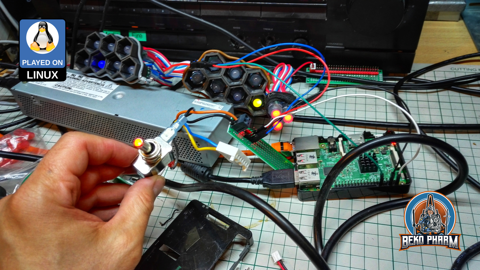
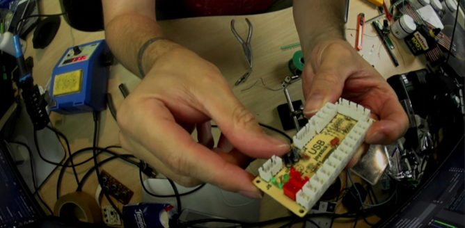
This video is how I gutted my already modified old Thrustmaster F-16 FLCS joystick of my ViperPit and made it work again with the help of an Arduino Pro Micro. This flight stick (and also the other peripherals) do belong in a museum but where’s the fun in that? I modified it and now it’s a generic USB joystick that works on any recent system. I focus mostly on the 5×5 button matrix since this is the hardest part to understand. In the end are a few minutes of playing X4 Foundations with it to give it a good test run. Now it just needs some oil for the creaking 😅
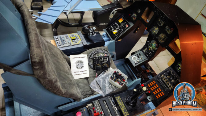
Oh boy oh boy it arrived. And what a friendly seller 👌 Kinda a shame that they gave up this hobby. Sold everything for an apple and an egg. It’s a #ViperPit#SimPit loosely based on a F-16. Nothing of this is functional though. Yet.
Winter may come!
Man… the _feel_ of those lovely switches and dials alone ❤️
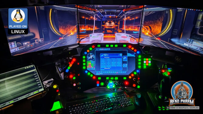
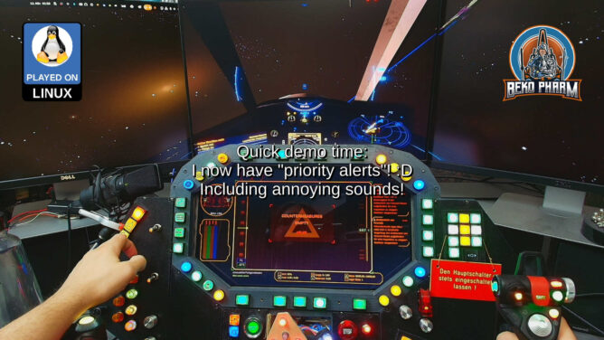
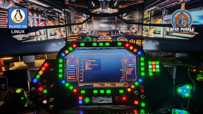
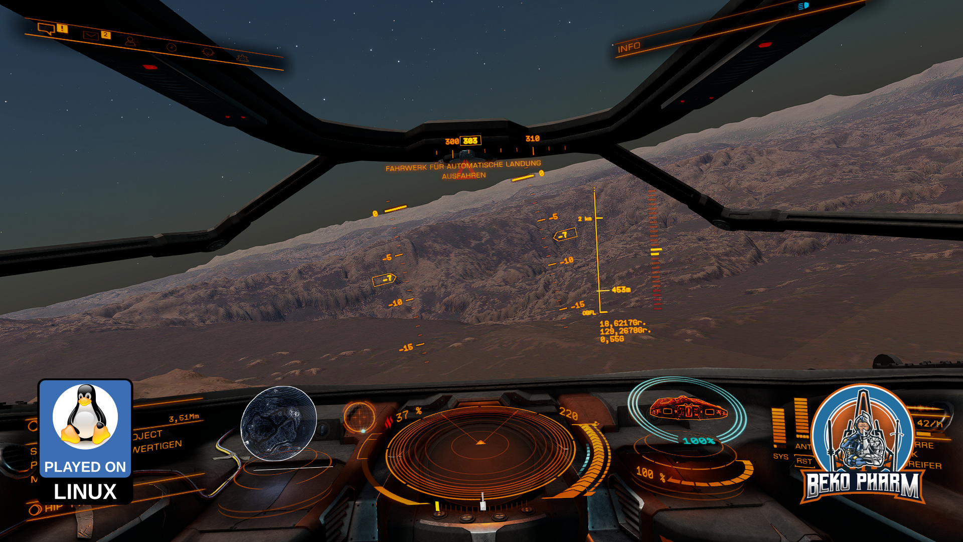
I hacked a mod for X4: Foundations to get ship telemetry and targeting data to my “Primary Buffer Panel” via a socket. This is a demonstration of my simulated cockpit made from cardboard on a budget usually used to play Elite Dangerous now also used for X4: Foundations. This is work in progress.
My DIY cockpit for X4: Foundations (on Linux PC)
In use:
A Linux PC
A DIY Headtracker
A DIY Joystick (My Primary Buffer Panel)
A X52 Pro HOTAS
An AMD RX6700XT
…a lot of plumbing in Node-Red xD
This is loosely based on the Python Pipe Server mod for X4 that is sadly Windows only using Named Pipes. I fixed that for Linux PC by side-loading the library LuaSocket and starting a socket server directly in X4. That’s right, the Python Server is simply not needed now and companion tools may directly connect to the socket. It’s a nice bonus that LuaSocket also allows a UDP or TCP server depending on how it is started. That was some piece of work though and I’m still wrapping things up to publish my code changes. I’m also still looking for testers so if you’re interested get in touch!
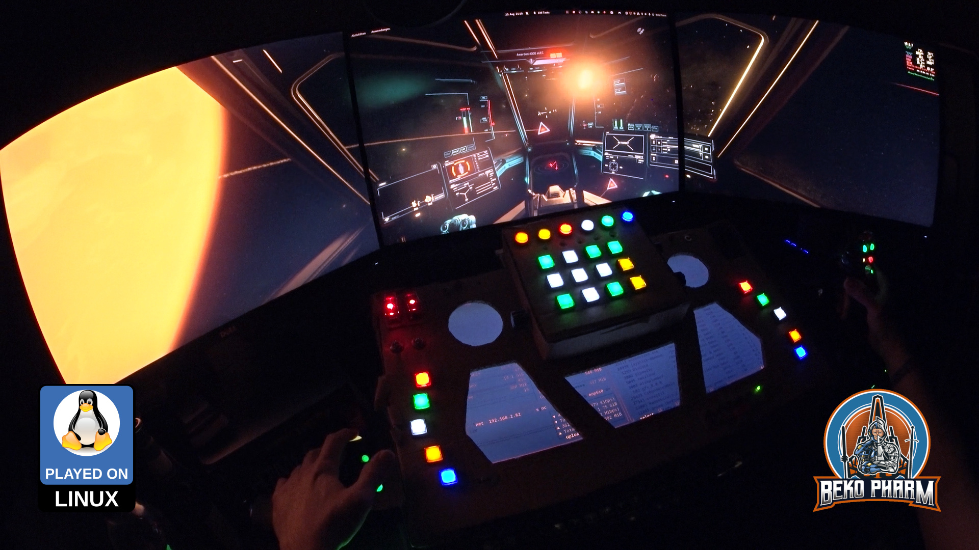
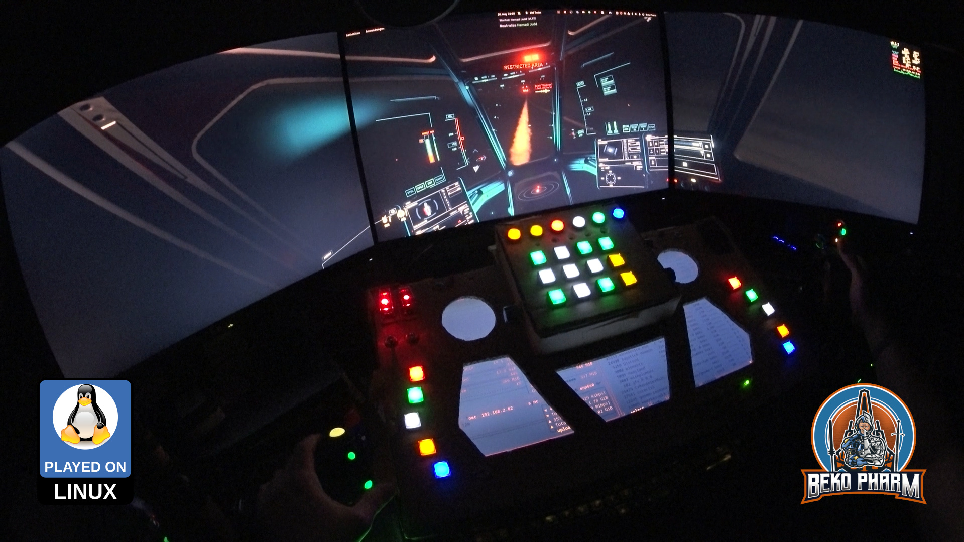
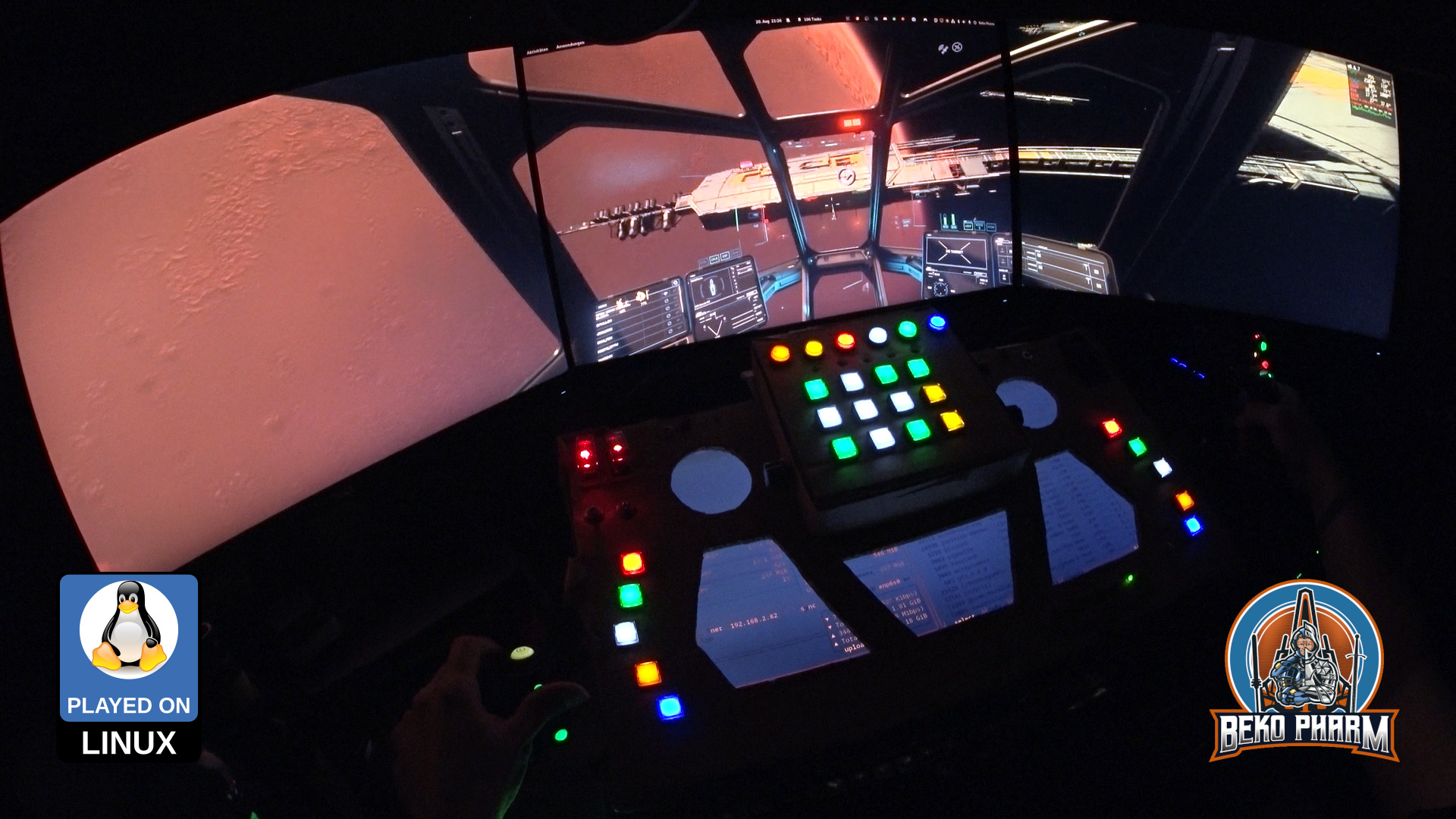
A lot happened since my last update on the simpit – under it’s hood. Function wise it changed not so much so the older demonstration video is still better for a quick demo. I still assembled a new video from clips of the first evening with the new hardware:
Quick trip from Armstrong Orbital over to the huge crater on HIP 117029-4 and back
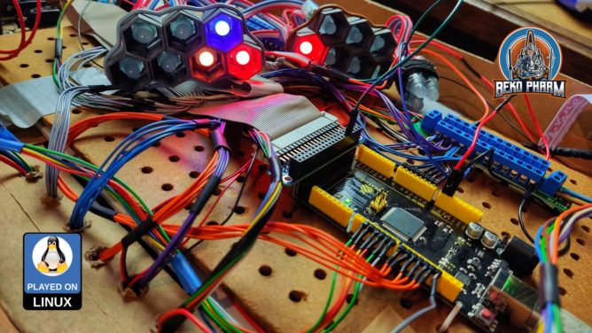
So what changed? I got rid of the CY-822A USB joystick controller that, while good, was also limiting. Especially in inputs and how they would react. The Raspberry Pi, that I used to drive the status indicators, is also gone. This is all replaced by one single Arduino Mega that is connected via serial over USB.
A custom joystick daemon written in Rust is listening for data from the #Arduino and feeds back the flags of Elite Dangerous to drive the blinken lights. I also extended the source to add me some rotary encoders (with push button function) and I’m very happy with the result of this. That makes a whopping amount of 48 buttons and 6 axis (where 2 axis make one hat). And it feels _so good_ to have e.g. self destruct or eject cargo save under a protective cover now 😀
An enemy vessel exploded, the bounty is mineThat rocket was too close for comfortLimping to a hangar after taking battle damageEvading a firestorm from behind by moving sidewaysVarious screenshots from a gaming session of StarCitizen
The panel also got an external PSU with enough ampere to drive as many LED as I may imagine so I no longer abuse a phone charger for that or risk frying of the PCB / USB.
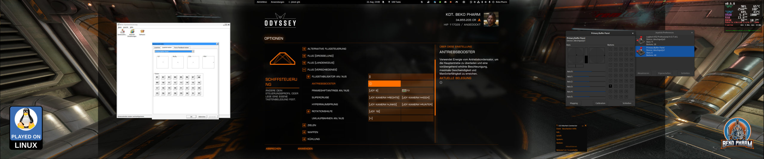
With all that in place I streamlined my pre-flight check-list quite a lot because way less hardware is involved and most of this is automated by now. It wasn’t all fun n giggles tho and while the new hard- and software “just worked” in e.g. #StarCitizen it was #EliteDangerous that gave me a hard time to actually use most of the new buttons.
Getting all the precious buttons into Elite as well (okay, limited to 32 thanks to an old dinput library but who is counting at this point – will simply set the rest to keyboard macros instead)
Turns out it had no idea about the device and model identifiers reported by the joystick daemon and that the kernel assumed a gamepad based on declaring e.g. ButtonNorth via the more recent xinput system really didn’t help – because that limited the amount of read buttons via xinput severe! In the end I set it’s identifier to a “vJoy” device. That I found in the DeviceMappings.xml of Elite and since this could be basically anything I gave it a try (and removed all “offending” magic gamepad buttons from the code) and sure enough Elite started accepting the inputs as expected and from there it was smooth sailing – got even the hat working.
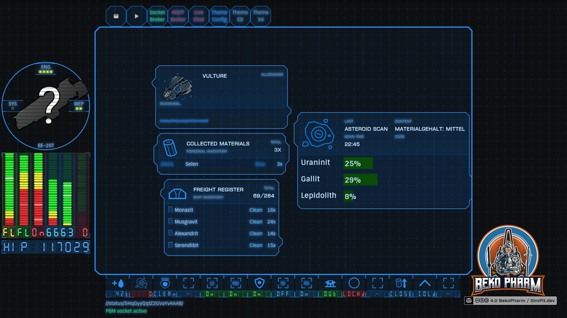
Oh and for everyone who is wondering what exactly they are seeing on the “MFD” when I’m playing Elite: That’s basically a Website using the #Arwes FUI framework. Find a quick demo video here. Without the cardboard covering up parts of the screen it looks basically like this:
What the game showsWhat the ARWES website shows as MFD
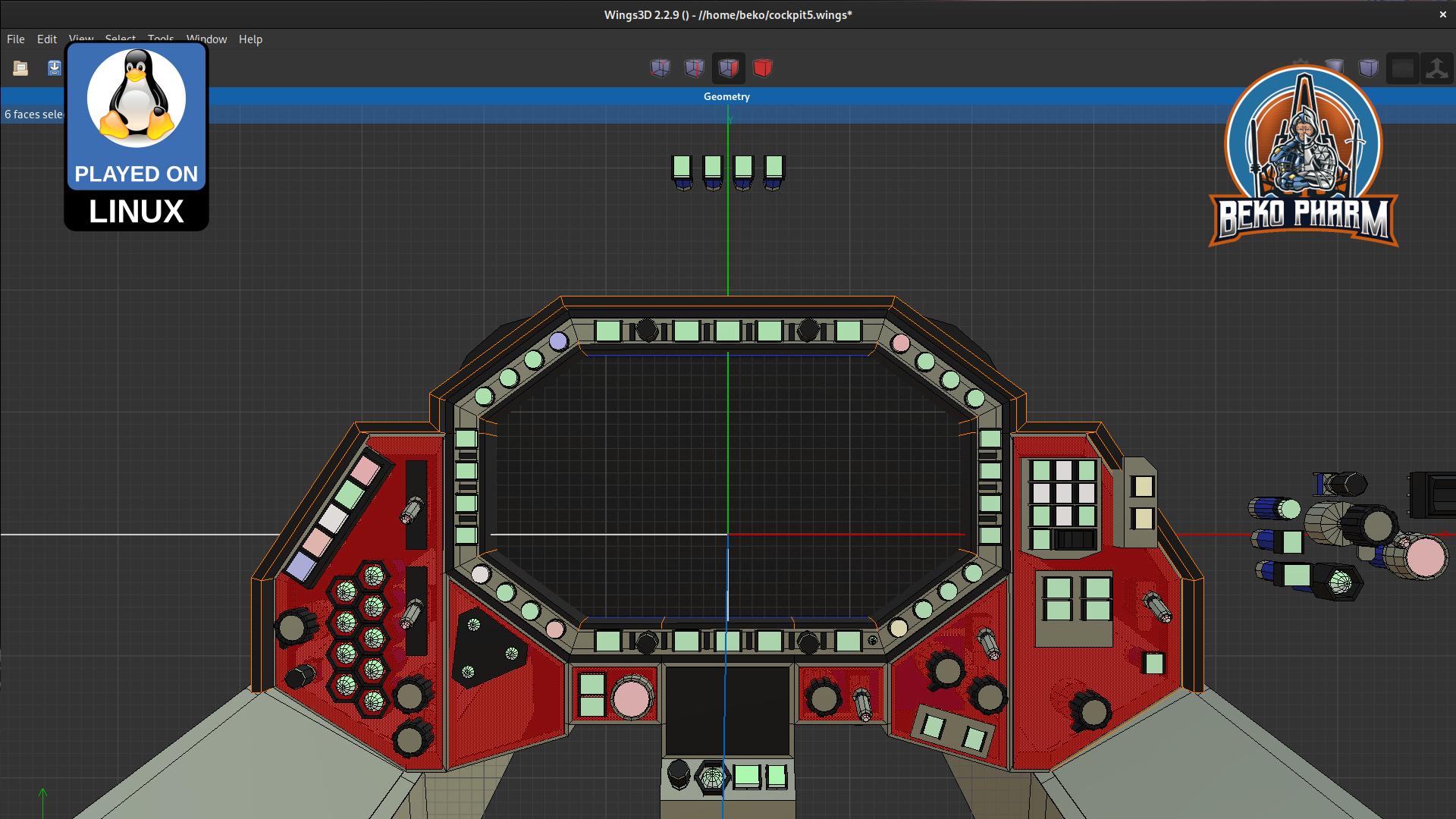
I also started doodles for a version 2 – now that I have an idea what I really want.
Plans for another #SimPit based on a #Macross Valkyrie Cockpit
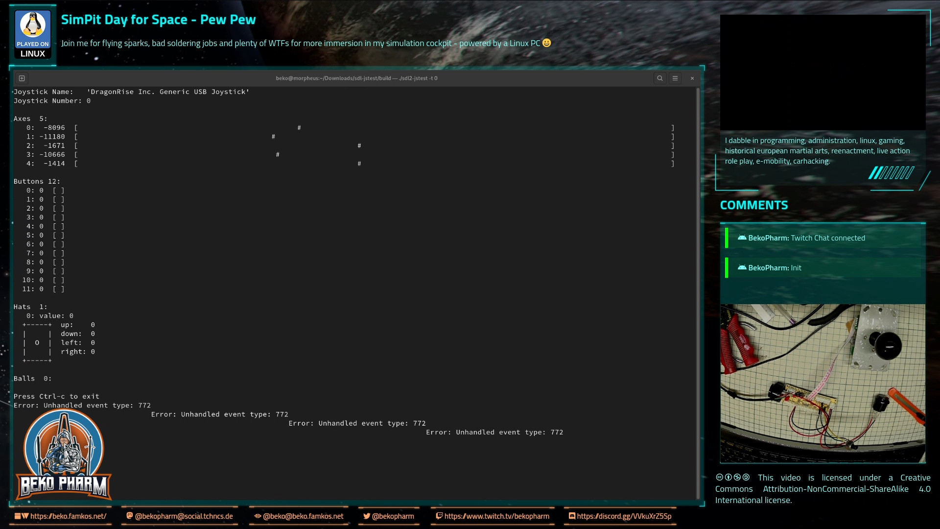
This is a brief description how to mod an CY-822A USB joystick controller into accepting analogue input. I’ve done this modification now with two of my PCBs and worked with both for an extended period of time without any problems. To achieve this two things have to be done – at your own risk!
sdl2-jstest detected 5 axes
The PCB comes with 5 analogue axes according to my Linux PC and sdl2-jstest and while I’m not sure where the 5th is located a tiny modification will allow us to use at least 4 of the axes.
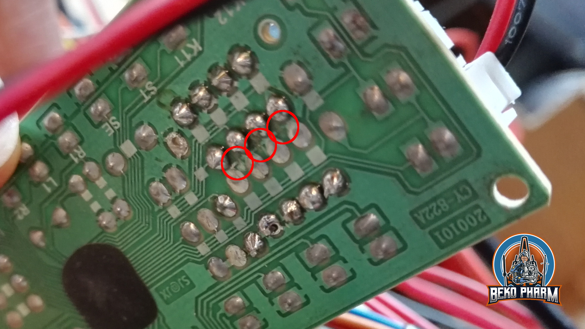
Locate the central lane and simply scratch off the track with a sharp knife at the 3 indicated positions.
Locate the resistors R1 – R8 on the front that make up for 4 possible connections for analogue input with the use of potentiometers. There are 2 resistors with ~10k on the PCB that have to go. The 2 resistors hold 4 of the 5 axes perfectly still in the centre because the middle lane is bridged on the backside. This is the part where the conductor path has to be interrupted. Locate the central lane and simply scratch off the track with a sharp knife. Also clean all the holes of R1 to R8 so you can solder in some new pins for easier access. Use a multimeter to make sure that none of the 4 central soldering points are connected with each other any more. The upper and lower ones stay connected (Plus and GND).
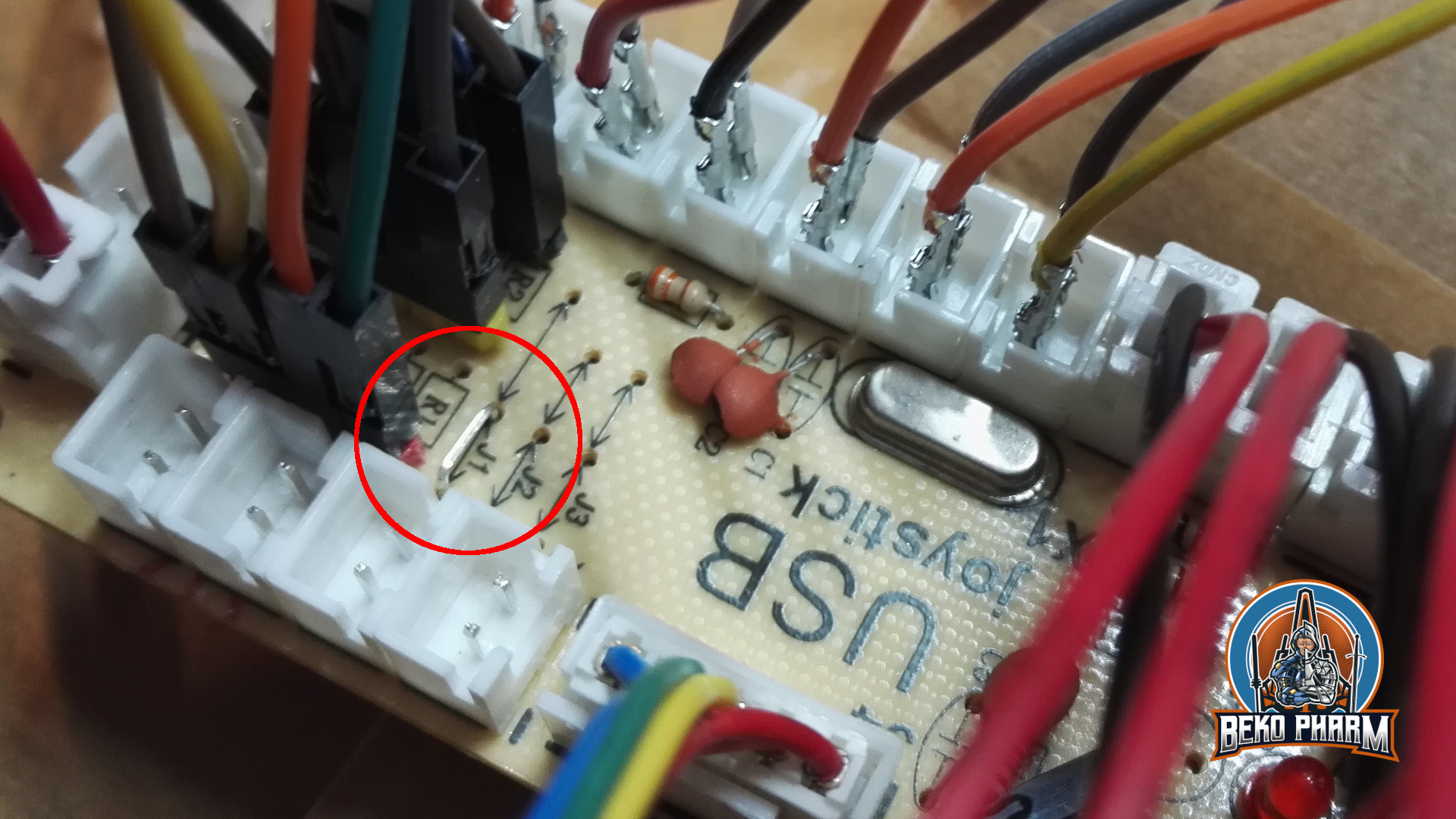
The wire bridge at J1 makes the board boot in analogue mode
Next we want to remove the zero ohm resistor at J1 and add a wire bridge instead. Look for an resistor with a single black ring next to R2, remove it, and solder in the wire bridge next to R1. This is basically a jumper setting but with a bridge. I’ve no idea why the designer went with a zero ohm resistor and not with a bridge. My only guess is that this was cheaper for the assembly machines.
Anyway, this will make the board boot in analogue mode so we do not have to use a mode switch on power on every time. This serves two purposes: Axes are now read from input and actually send as joystick events on the USB wire while the former digital joystick connector (5 pins) is now mapped to Up/Down/Left/Right buttons – so no extra buttons are needed here any more (but can still be added, of course).
Any potentiometer should do – mine are 100k – 200k. YMMV.
Now it’s time to connect potentiometers as analogue inputs. This is pretty straight forward. Just make sure that the central connector goes to the centre of each axes. Change the upper with the lower pin if the direction is not as desired.
Please note that any axes that has no input attached will report _a lot_ of jitter making your game/app go nuts. This is what the former resistors at R1 and R2 were there for.