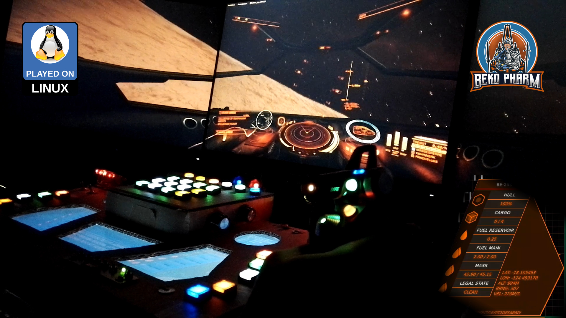
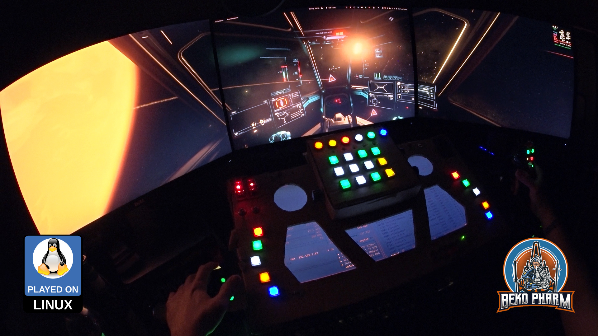
A lot happened since my last update on the simpit – under it’s hood. Function wise it changed not so much so the older demonstration video is still better for a quick demo. I still assembled a new video from clips of the first evening with the new hardware:

Quick trip from Armstrong Orbital over to the huge crater on HIP 117029-4 and back

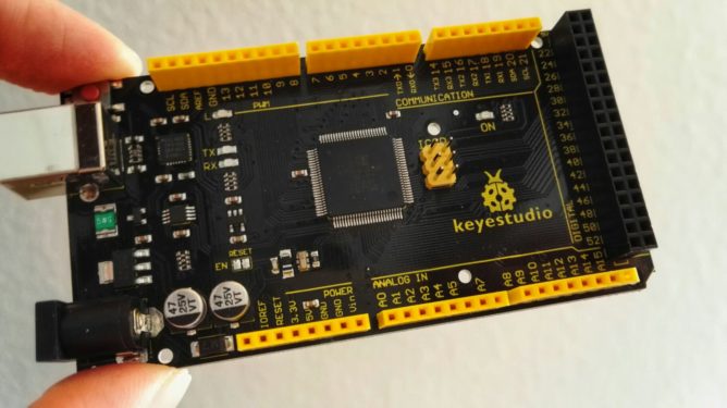
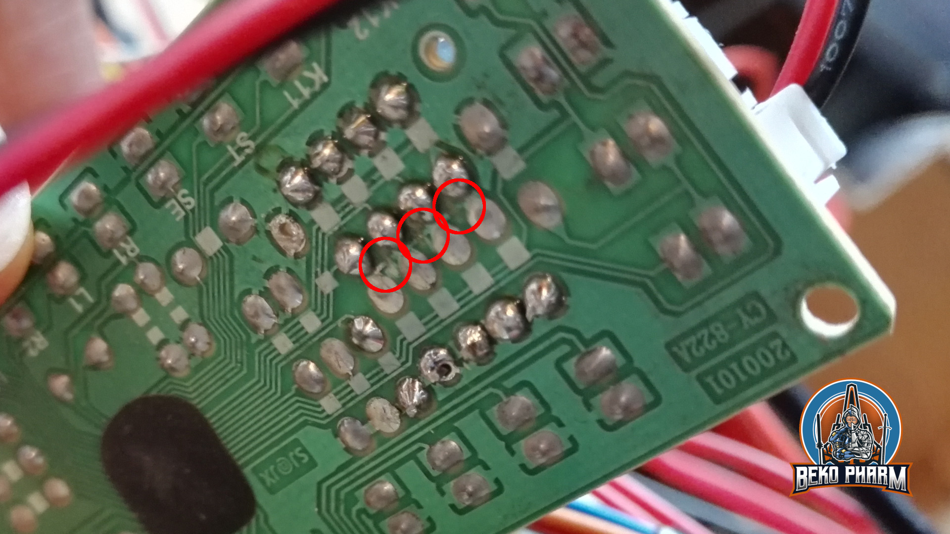
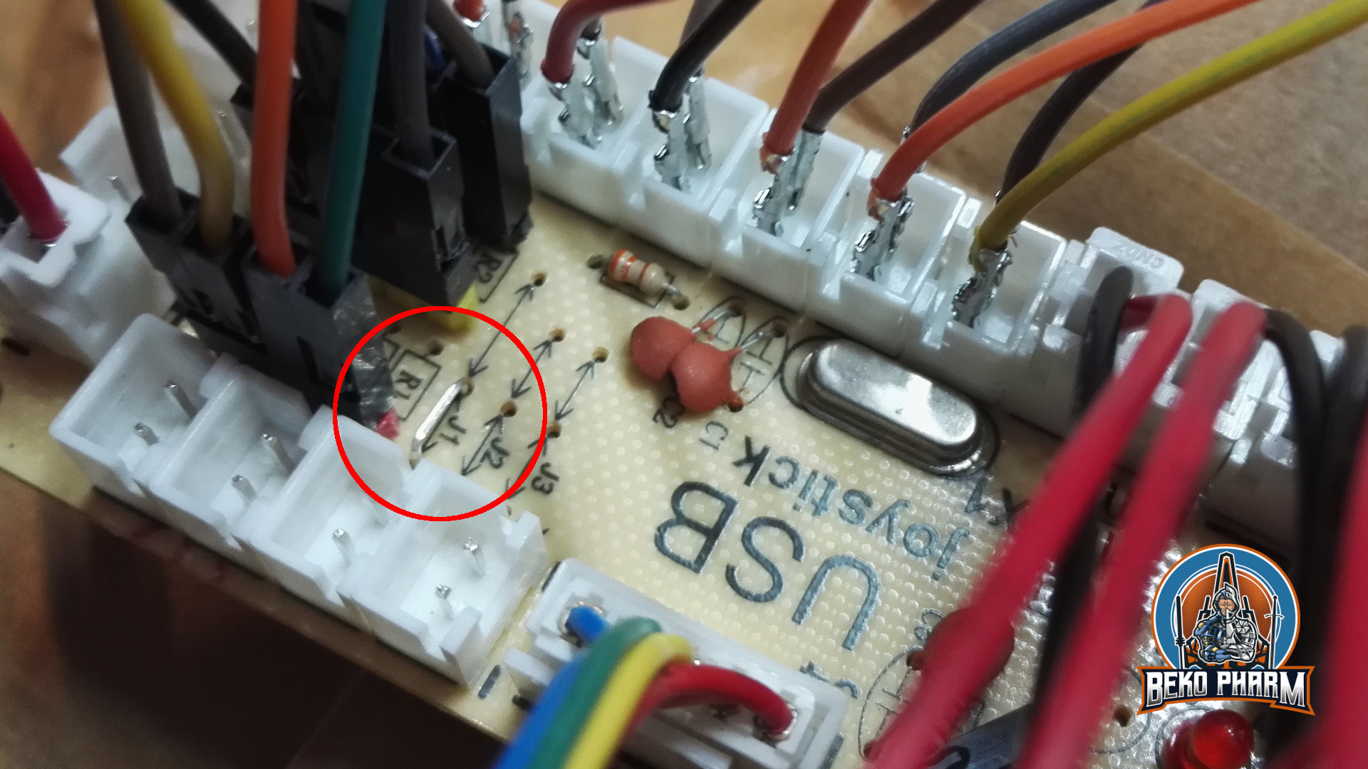
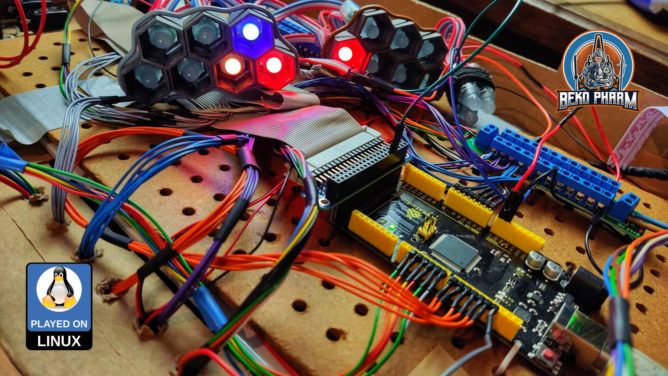
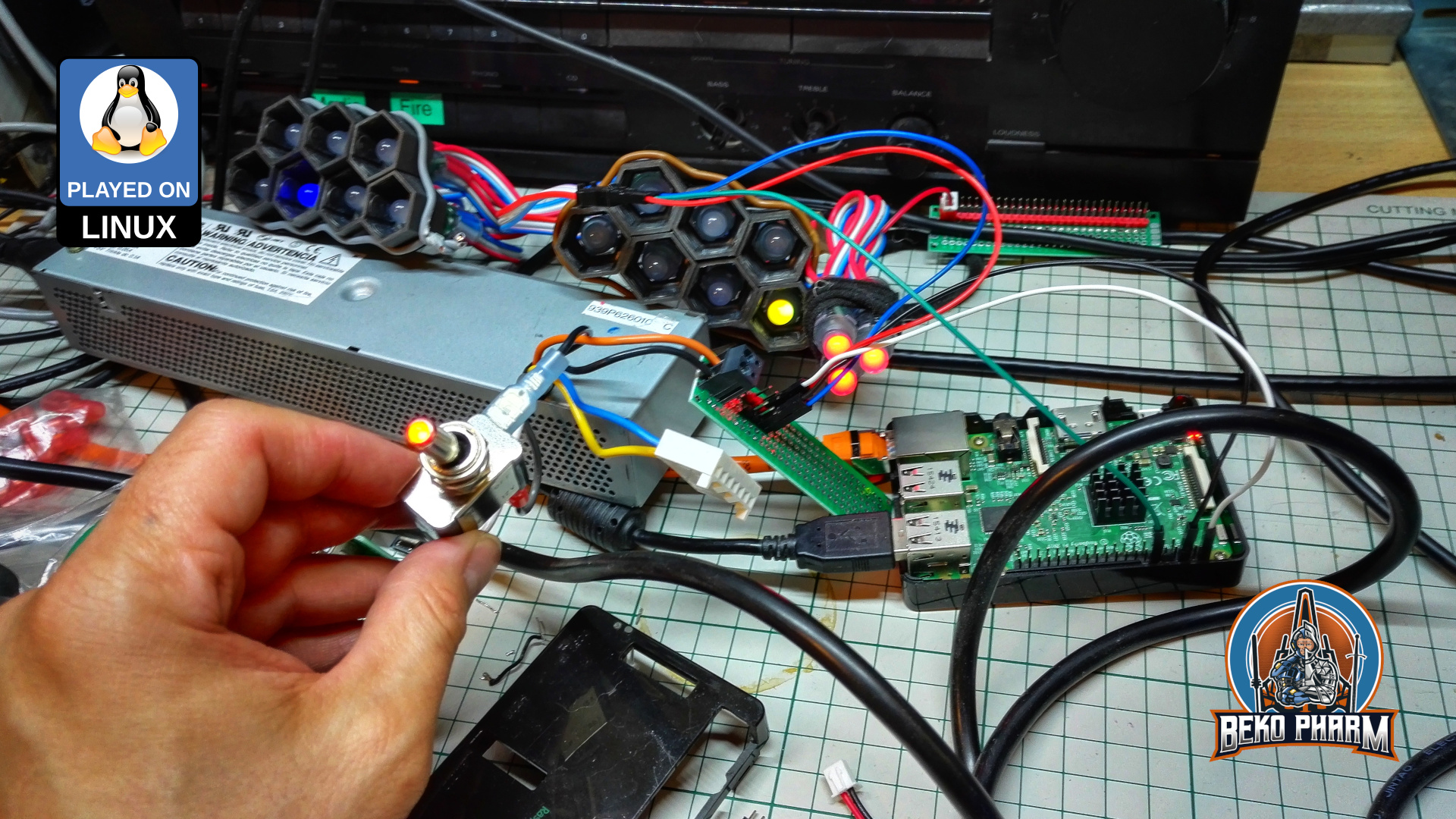
So what changed? I got rid of the CY-822A USB joystick controller that, while good, was also limiting. Especially in inputs and how they would react. The Raspberry Pi, that I used to drive the status indicators, is also gone. This is all replaced by one single Arduino Mega that is connected via serial over USB.

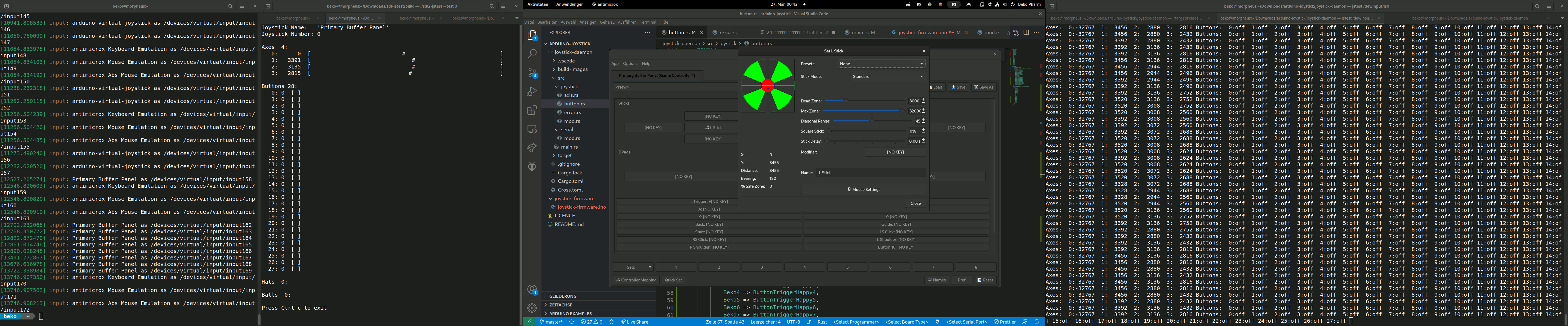
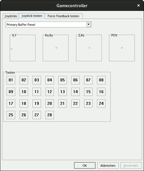
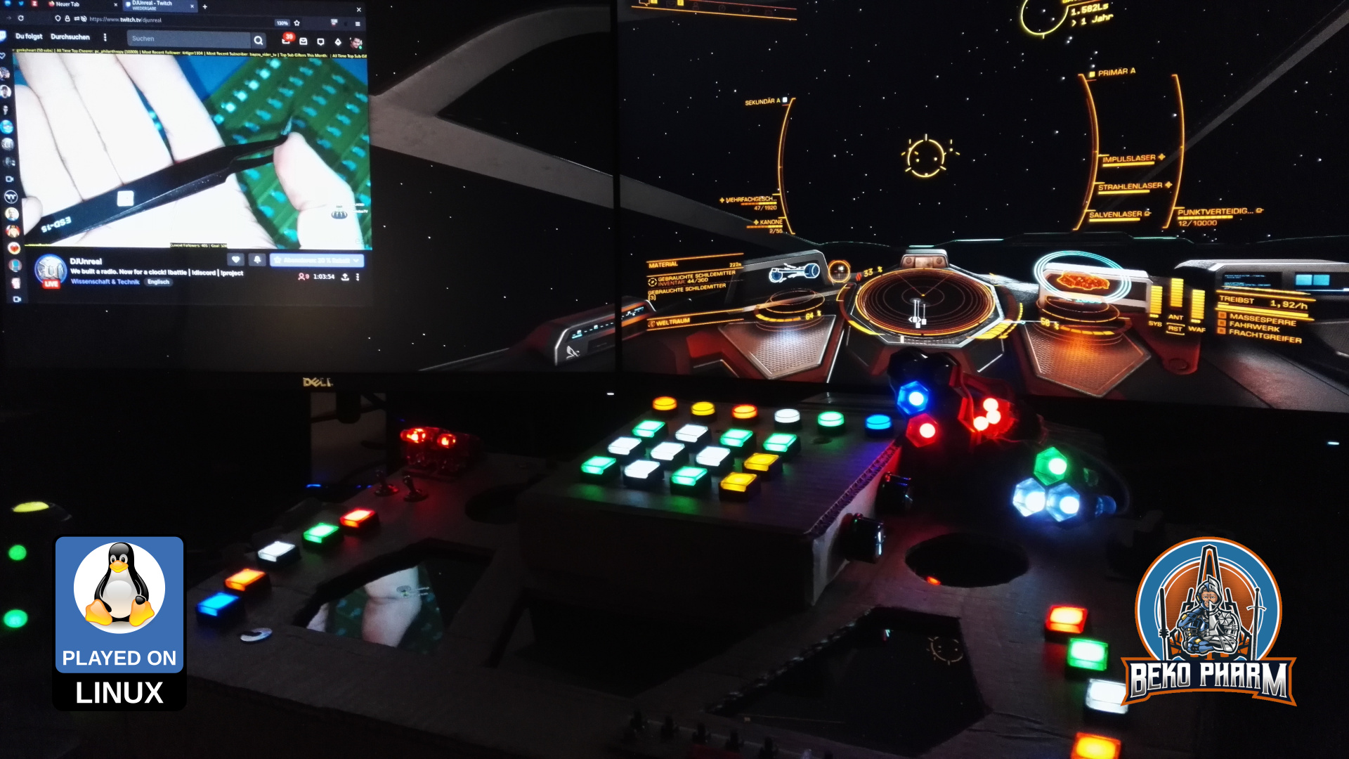
A custom joystick daemon written in Rust is listening for data from the and feeds back the flags of Elite Dangerous to drive the blinken lights. I also extended the source to add me some rotary encoders (with push button function) and I’m very happy with the result of this. That makes a whopping amount of 48 buttons and 6 axis (where 2 axis make one hat). And it feels _so good_ to have e.g. self destruct or eject cargo save under a protective cover now 😀

The panel also got an external PSU with enough ampere to drive as many LED as I may imagine so I no longer abuse a phone charger for that or risk frying of the PCB / USB.

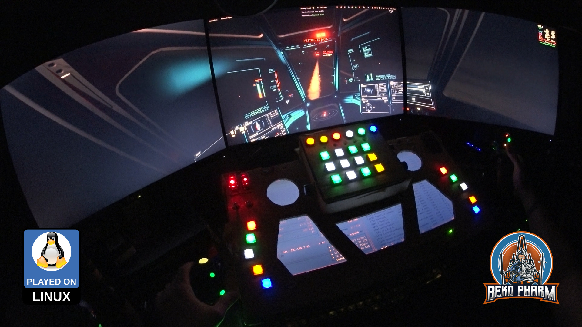
With all that in place I streamlined my pre-flight check-list quite a lot because way less hardware is involved and most of this is automated by now. It wasn’t all fun n giggles tho and while the new hard- and software “just worked” in e.g. it was that gave me a hard time to actually use most of the new buttons.

Getting all the precious buttons into Elite as well (okay, limited to 32 thanks to an old dinput library but who is counting at this point – will simply set the rest to keyboard macros instead)

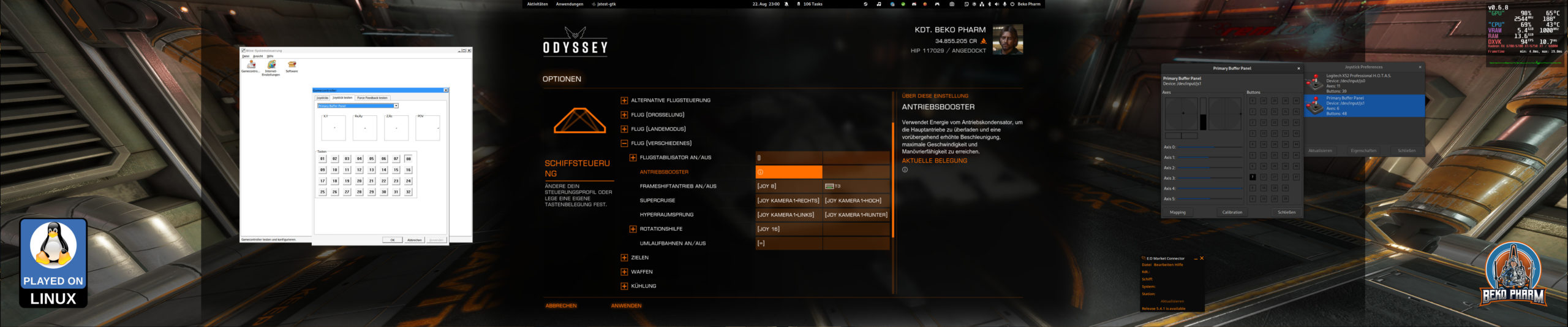
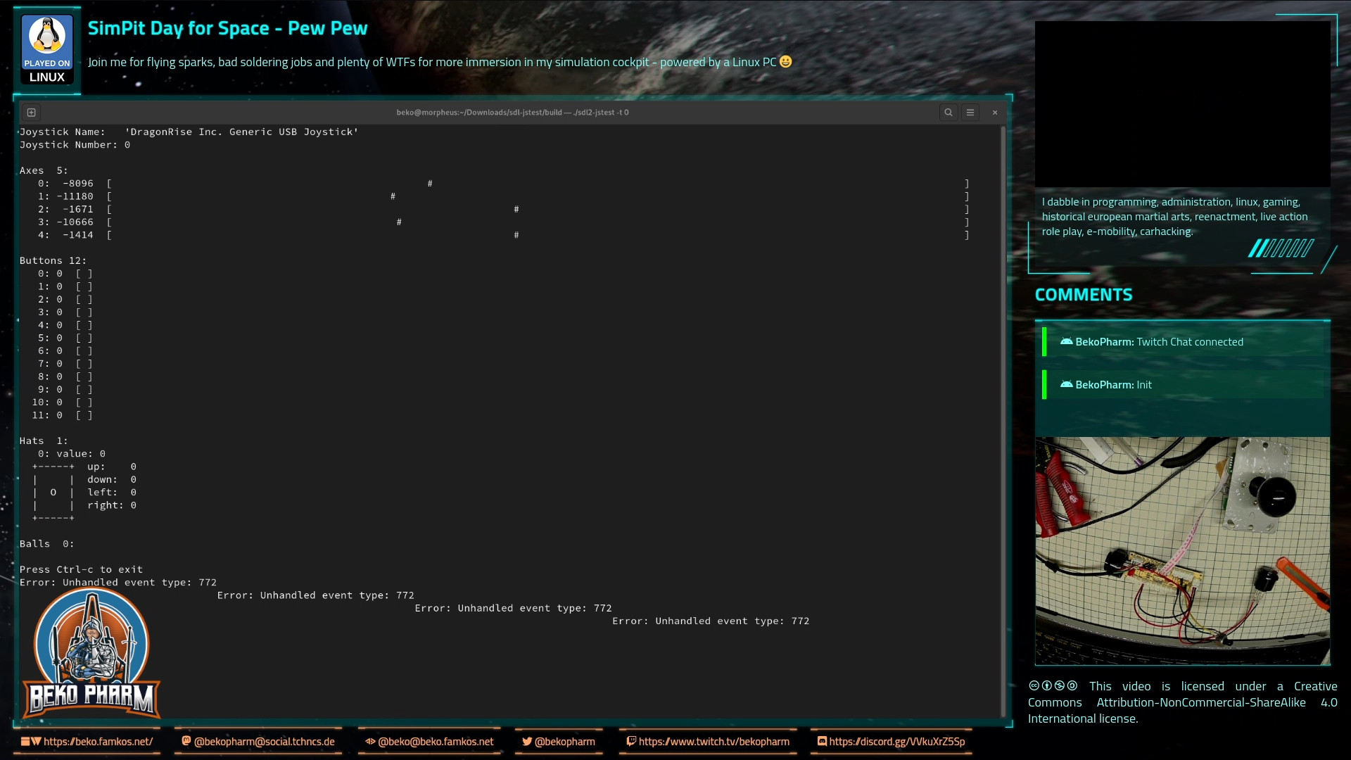
Turns out it had no idea about the device and model identifiers reported by the joystick daemon and that the kernel assumed a gamepad based on declaring e.g. ButtonNorth via the more recent xinput system really didn’t help – because that limited the amount of read buttons via xinput severe! In the end I set it’s identifier to a “vJoy” device. That I found in the DeviceMappings.xml of Elite and since this could be basically anything I gave it a try (and removed all “offending” magic gamepad buttons from the code) and sure enough Elite started accepting the inputs as expected and from there it was smooth sailing – got even the hat working.

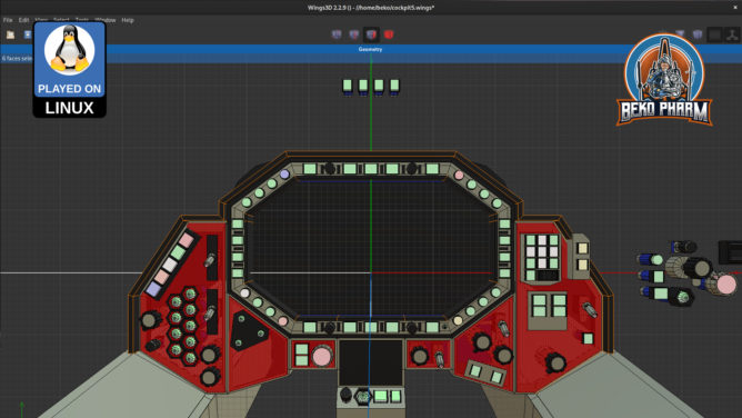
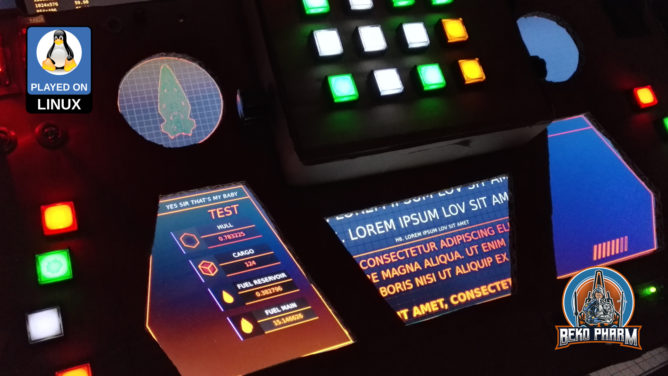
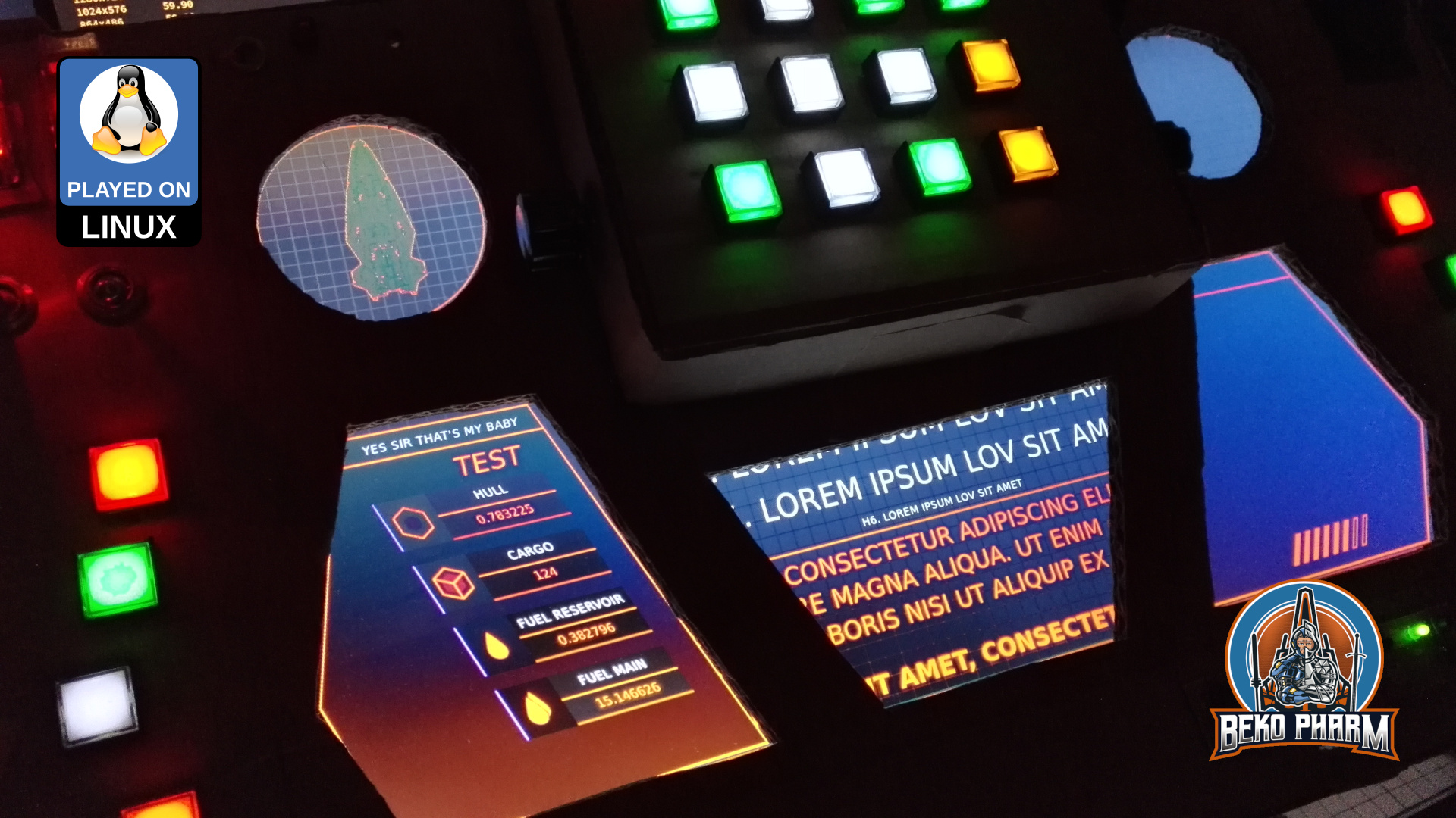
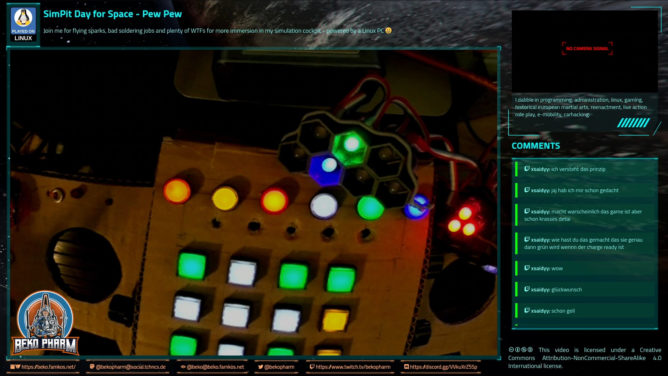
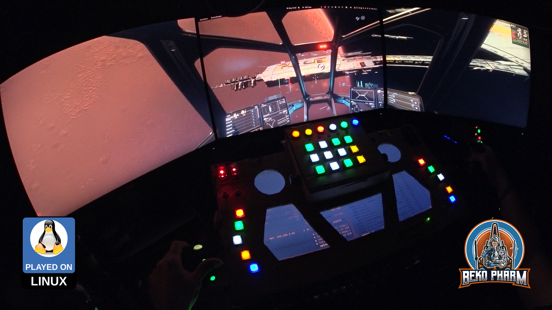
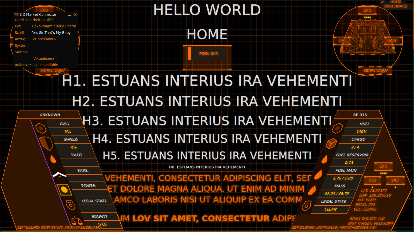
Oh and for everyone who is wondering what exactly they are seeing on the “MFD” when I’m playing Elite: That’s basically a Website using the FUI framework. Find a quick demo video here. Without the cardboard covering up parts of the screen it looks basically like this:

I also started doodles for a version 2 – now that I have an idea what I really want.

Plans for another based on a Valkyrie Cockpit

You probably heard about this before: An Arduino can be made into an excellent DIY joystick. Most examples use a Leonardo or Micro for this for a very good reason. They one comes basically with a chip that is recognized as HID (Human Interface Device) hardware on any modern operating system.

This is not the case with a Mega. This one has other perks but HID it is not. It sure shows up as USB device and a ttyUSB is raised where serial communications with the Arduino can be initiated. I’m also aware that some flash the built in programmer of the Mega so it starts operating like the others (which obviously removed the built in programmer). I’m on Linux PC though so I thought it’s basically a job of tricking the system into recognizing it as joystick and call it a day and OMG was I wrong!

How it’s not done

My train of thoughts was like this: Linux still supports plenty of old serial joysticks so how complicated can it be to send some bits an existing driver recognizes. Old hardware like this is usually glued to the driver with the tool inputattach of the Linux Console Project. This does basically initialise a joystick on some serial connection and sends it off to a fitting kernel driver. This way even non-USB, or let’s better say non-HID hardware, is mapped to a kernel driver who in return will set-up the joystick subsystem and manage the communication with the stick via a serial connection.

Turns out I’m not the first one with that idea and apparently someone made it work by connecting old Playstation Controller and a Wii Classic Controller to an Ardunio and fake a Stinger device without the use of HID so Kudos to Jarno Lehtinen here and his Linux-Arduino-Serial-Joystick repo – you sure did sent me down a rabbit hole of horror and amazement. I couldn’t even get inputattach to wait for that magic string to be sent with anything else than 9600 baud and aligned stars! I also had to throw socat into this horrible mix because the Arduino would insist on rebooting on init so a timeout was guaranteed! In case you wonder how I did this:

socat -r left.raw -R right.raw pipe:/dev/ttyUSB0 PTY,link=/dev/ttyUSB1,rawer
# and xdd to show me the debug juice
tail -f left.raw | xxd -c4
# and on yet another terminal
inputattach --baud 9600 --stinger /dev/ttyUSB1

This also meant that I had to tear everything down for reprogramming the Arduino. Anyway, in the end I could finally get through that init phase where the stinger related code in inputattach is waiting for the magic key after sending “ E5E5” to finally load the Stinger kernel driver – communication for both ways confirmed!

    // "\r\n0600520058C272";
    byte byteResponse[] = {0x0D, 0x0A, 0x30, 0x36, 0x30, 0x30, 0x35, 0x32, 0x30, 0x30, 0x35, 0x38, 0x43, 0x32, 0x37, 0x32};
    if (Serial.availableForWrite() >= sizeof(byteResponse))
    {
      Serial.write(byteResponse, sizeof(byteResponse));
    }

At this point I had a pipe to prevent the timeout due to the resetting Arduino, the _only_ working baud rate 9600 I could figure out with the Mega, a loaded driver that was recognized as joystick and was sitting put and did… absolutely nothing. Null. Nada. Not a single bit made it to the driver and I could not figure out why. My guess is it needs a change in the baud rate to the original 1200 (?) of the Stinger but I have no idea if this is true. I could also not find any way how the stream is controlled and since the driver would fill up 2 bytes all the time and interpret them there is a fair chance that it would simply be one byte off all the time. Speculations tho, I simply didn’t grasp the stinger.c source so this is all just a theory. I do not want to admit how much time I sunk into this and I was pretty frustrated at this point. Reading some stupid serial? Not like this! Too many hoops!

So I threw it all in the bin 🚮

How it’s probably done

Say hi to /dev/uinput where you can basically raise virtual devices, like a joystick, without [much?] pain. I’m not the first one, of course, and funny enough the reason behind is very similar to mine. Read more on Virtual joystick on Linux by Gwilym Kuiper where this is all explained in great detail. The referred code at https://github.com/gwilymk/arduino-joystick sure did help me to get started and even without having touched Rust ever before I was able to quickly adjust this for my needs, doubling the possible buttons and get it up and running in just a few hours for my Linux PC. Cheers mate (also Jarno Lehtinen – you teached me a lot that day :D) 🕹️

So here it is: A Mega acting as joystick without HID over a serial connection driven by a userspace daemon (means no kernel driver required) written in Rust providing a virtual uinput device for a joystick on the “modern” event system. Heck it’s even recognized in Wine!

What a journey to begin with. Now I need a back-channel for my blinky lights so I get my Raspberry Pi back from simpit duty 🙃

This is a brief description how to mod an CY-822A USB joystick controller into accepting analogue input. I’ve done this modification now with two of my PCBs and worked with both for an extended period of time without any problems. To achieve this two things have to be done – at your own risk!

sdl2-jstest detected 5 axes

The PCB comes with 5 analogue axes according to my Linux PC and sdl2-jstest and while I’m not sure where the 5th is located a tiny modification will allow us to use at least 4 of the axes.

Locate the central lane and simply scratch off the track with a sharp knife at the 3 indicated positions.

Locate the resistors R1 – R8 on the front that make up for 4 possible connections for analogue input with the use of potentiometers. There are 2 resistors with ~10k on the PCB that have to go. The 2 resistors hold 4 of the 5 axes perfectly still in the centre because the middle lane is bridged on the backside. This is the part where the conductor path has to be interrupted. Locate the central lane and simply scratch off the track with a sharp knife. Also clean all the holes of R1 to R8 so you can solder in some new pins for easier access. Use a multimeter to make sure that none of the 4 central soldering points are connected with each other any more. The upper and lower ones stay connected (Plus and GND).

The wire bridge at J1 makes the board boot in analogue mode

Next we want to remove the zero ohm resistor at J1 and add a wire bridge instead. Look for an resistor with a single black ring next to R2, remove it, and solder in the wire bridge next to R1. This is basically a jumper setting but with a bridge. I’ve no idea why the designer went with a zero ohm resistor and not with a bridge. My only guess is that this was cheaper for the assembly machines.

Anyway, this will make the board boot in analogue mode so we do not have to use a mode switch on power on every time. This serves two purposes: Axes are now read from input and actually send as joystick events on the USB wire while the former digital joystick connector (5 pins) is now mapped to Up/Down/Left/Right buttons – so no extra buttons are needed here any more (but can still be added, of course).

Any potentiometer should do – mine are 100k – 200k. YMMV.

Now it’s time to connect potentiometers as analogue inputs. This is pretty straight forward. Just make sure that the central connector goes to the centre of each axes. Change the upper with the lower pin if the direction is not as desired.

Please note that any axes that has no input attached will report _a lot_ of jitter making your game/app go nuts. This is what the former resistors at R1 and R2 were there for.

The last update has been a while. I focused my attention to the MFDs (Multi-function display). This part didn’t get much attention yet and I was caught between the difficult choice to learn yet another fancy framework, like Raylib, that would do OpenGL ES 2.0 without X11 on the Raspberry – or just throw the might of my CoffeeLake at it and go with ReactJS since most of the data was already available via NodeRED anyway. Also… ARWES is just so cool 🤩

I went with ReactJS and ARWES again, simply because I have some experience in this by know thanks to my Streaming Overlay I wrote with it. Hobbling it up to NodeRED was just a matter of installing SocketIO to transport the messages. It’s all a very hacky mess but it gets the job done.

Video demonstration of my simulated cockpit made from cardboard on a budget mainly used to play Elite Dangerous in early 2022. This is work in progress.

While seeking through the available data I noticed that I don’t get velocity values from Elite. That’s not so important in space but _kinda_ interesting for me in planetary flight to satisfy the flight sim gamer in me as well. I noticed tho that I do get timestamped latitude, longitude and altitude values so shouldn’t it be possible to “simply” calculate this, right? Right?

This was when I dived into the rabbit hole of calculating velocity and heading on planetary objects using a spherical coordinate system and while I didn’t nail it exactly how Elite does it the result is close enough. The game provides the required data to go crazy here – most important the radius of the current object. In _theory_ I could start writing some primitive AFS (Auto Flight System) routines now, which I’m totally going to explore at some point in the future just because 🤓

Checking my maths – yes, altitude is added to the mix so velocity is mostly correct as long as no rapid course changes are made

After spending way too much time with this and the Pythagorean theorem (Yes mum, a game made me do maths. MATHS! 🤯) I settled with some calculations and data for my current ship to the right and targeted ship data on the left. This is sort of tricky because many game events update different parts of the data so timestamps have to be kept in mind and a game specific parsing strategy is required. See the last part of the demonstration video to get an idea how this looks.

Improving situational awareness by putting the video feed of wingman / gunner on the central MFD.

Another point to tick off my list was getting the head tracking to work in Elite (again). Now this is very Linux PC specific so you may tune out on this paragraph. On Linux PC I’d usually compile Opentrack with the Wine Glue, patch in my appdata dir for Proton and hope that it’s still ABI compliant to Just work™. Alas recent Proton is sandboxed within pressure vessel and the usual approach of memory mapping is simply no longer working, if I got the gist of this right.

So my _current_ strategy is to download and drop the Windows build of Opentrack into the game folder and chain-load the EXE with the game where the Opentrack EXE would listen on UDP while my native Opentrack BIN would send via UDP. A task not made easy with Proton but it is possible. The following snippet may give you some pointers:

#!/bin/bash
export STEAM_COMPAT_DATA_PATH=/games/steam/steamapps/compatdata/359320
export STEAM_COMPAT_CLIENT_INSTALL_PATH="$HOME/.steam/steam"
python3 /games/steam/steamapps/common/Proton\ -\ Experimental/proton run opentrack.exe

Why running Opentrack twice? The native build performs a lot better with my webcam and every frame really count here. Reading data via UDP is not much of a burden for Proton. This also saves me the trouble of fiddling with Wine Glue, a painful compile process nobody should endure involving installation of many many additional 32bit libraries. Hilarious but it works.

Did some programming on my “MFDs” last night. They start coming to live with proper game data from 😁 All duct tape and JS plumbing. Sorry for shaky cam. Couldn’t be arsed with the tripod at 1:30 am.

Short demo video of the panels loading up

Here is a close up picture without all the shaking:

The animations are made possible with ARWES.dev – a library designed to create futuristic user interfaces (FUIs) fast.

This is the result of a live stream where I’m implementing my proof of concept of using a Neopixel string as status indicators for Elite Dangerous in my SimPit.

It was a mixed stream of GER/ENG (subtitles to follow) and consists of three parts: Reproducing the proof of concept, implementing the solution with a whopping amount of 17 LED indicators and finally a test run in the game at the end.

Jump to 36:00 for Neopixel action with Elite Dangerous: Odyssey