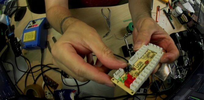
This is a brief description how to mod an CY-822A USB joystick controller into accepting analogue input. I’ve done this modification now with two of my PCBs and worked with both for an extended period of time without any problems. To achieve this two things have to be done – at your own risk!

sdl2-jstest detected 5 axes

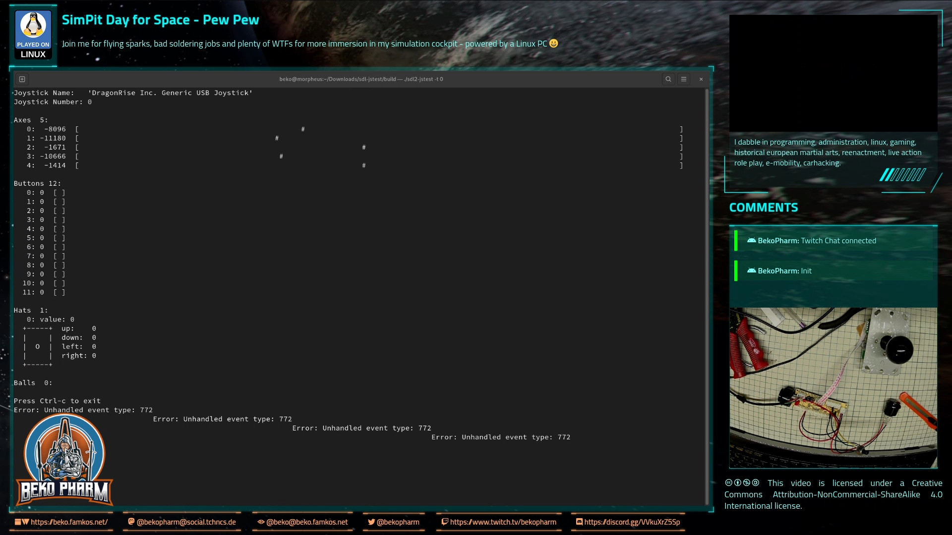
The PCB comes with 5 analogue axes according to my Linux PC and sdl2-jstest and while I’m not sure where the 5th is located a tiny modification will allow us to use at least 4 of the axes.

Locate the central lane and simply scratch off the track with a sharp knife at the 3 indicated positions.

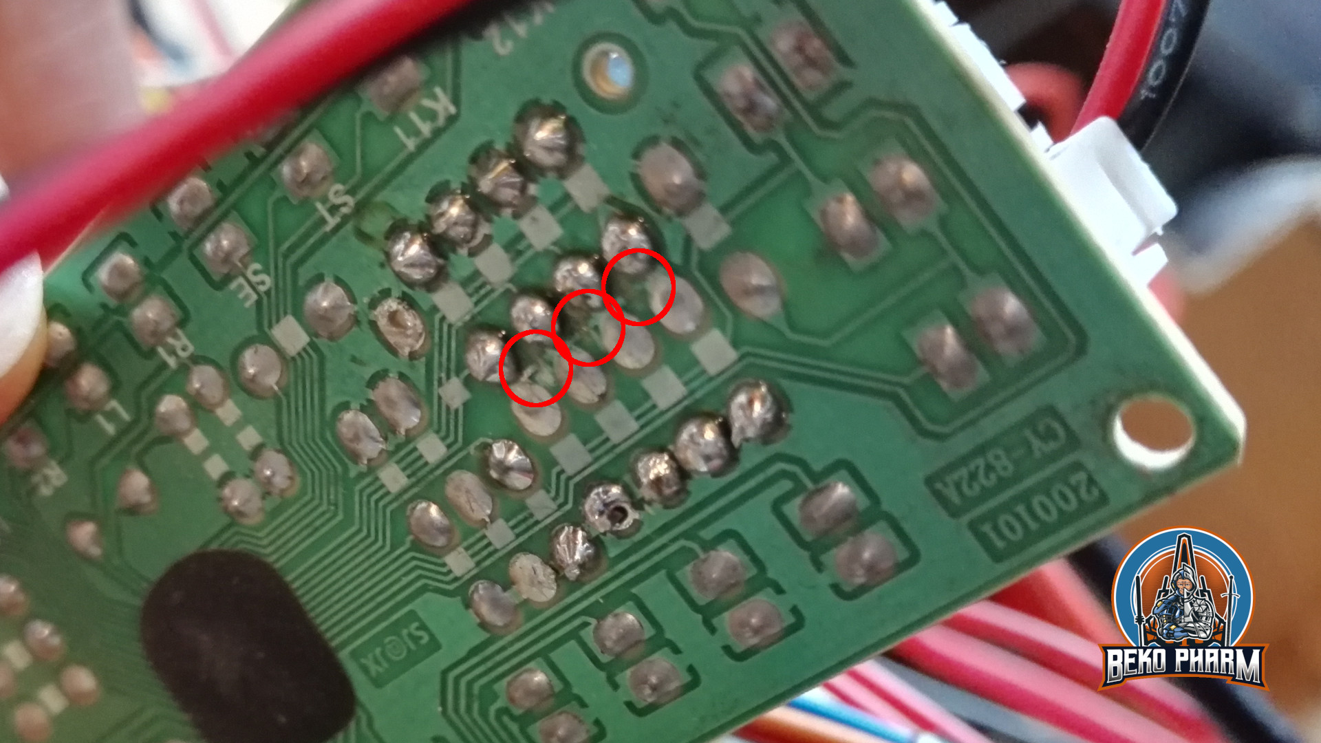
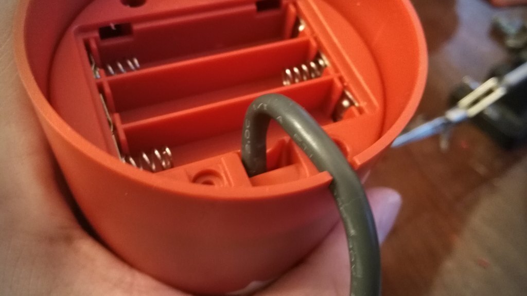
Locate the resistors R1 – R8 on the front that make up for 4 possible connections for analogue input with the use of potentiometers. There are 2 resistors with ~10k on the PCB that have to go. The 2 resistors hold 4 of the 5 axes perfectly still in the centre because the middle lane is bridged on the backside. This is the part where the conductor path has to be interrupted. Locate the central lane and simply scratch off the track with a sharp knife. Also clean all the holes of R1 to R8 so you can solder in some new pins for easier access. Use a multimeter to make sure that none of the 4 central soldering points are connected with each other any more. The upper and lower ones stay connected (Plus and GND).

The wire bridge at J1 makes the board boot in analogue mode

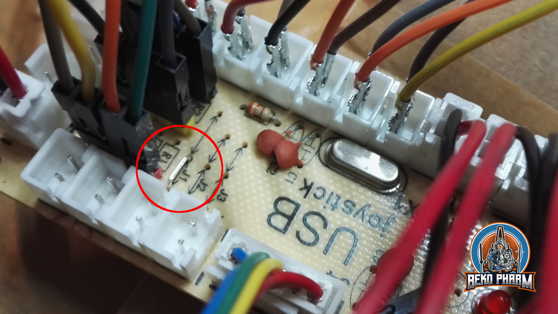
Next we want to remove the zero ohm resistor at J1 and add a wire bridge instead. Look for an resistor with a single black ring next to R2, remove it, and solder in the wire bridge next to R1. This is basically a jumper setting but with a bridge. I’ve no idea why the designer went with a zero ohm resistor and not with a bridge. My only guess is that this was cheaper for the assembly machines.

Anyway, this will make the board boot in analogue mode so we do not have to use a mode switch on power on every time. This serves two purposes: Axes are now read from input and actually send as joystick events on the USB wire while the former digital joystick connector (5 pins) is now mapped to Up/Down/Left/Right buttons – so no extra buttons are needed here any more (but can still be added, of course).

Any potentiometer should do – mine are 100k – 200k. YMMV.

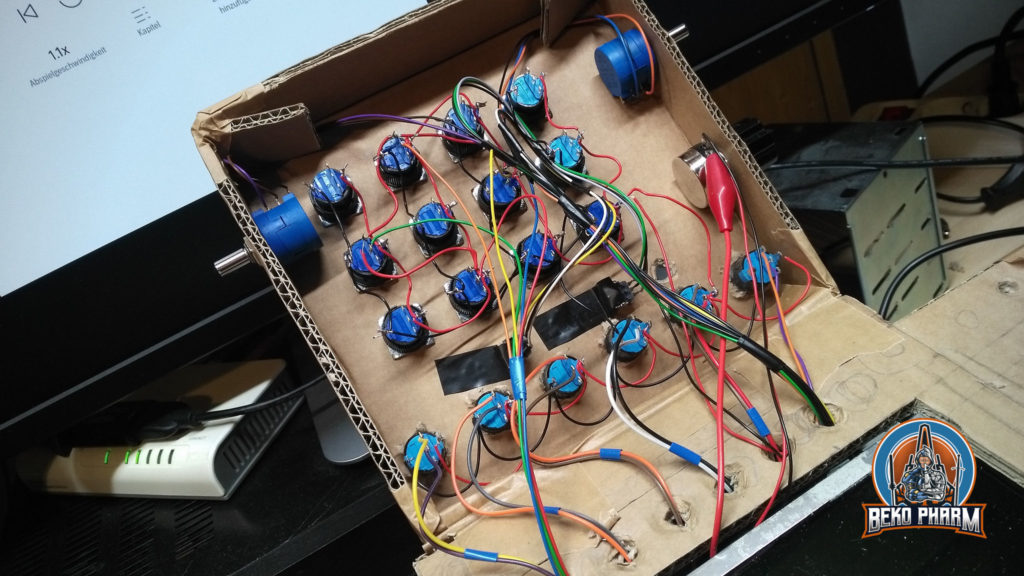
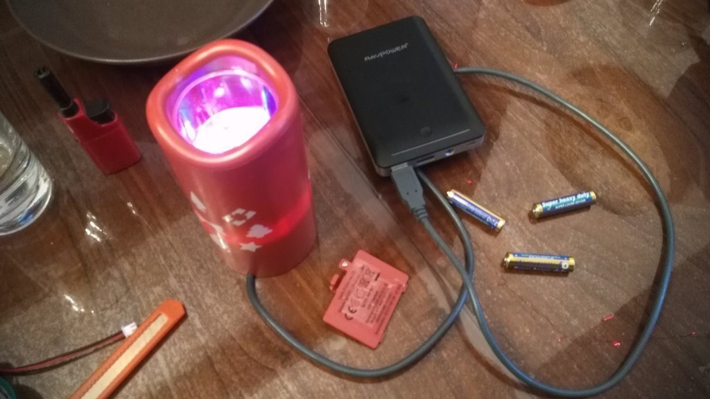
Now it’s time to connect potentiometers as analogue inputs. This is pretty straight forward. Just make sure that the central connector goes to the centre of each axes. Change the upper with the lower pin if the direction is not as desired.

Please note that any axes that has no input attached will report _a lot_ of jitter making your game/app go nuts. This is what the former resistors at R1 and R2 were there for.

The last update has been a while. I focused my attention to the MFDs (Multi-function display). This part didn’t get much attention yet and I was caught between the difficult choice to learn yet another fancy framework, like Raylib, that would do OpenGL ES 2.0 without X11 on the Raspberry – or just throw the might of my CoffeeLake at it and go with ReactJS since most of the data was already available via NodeRED anyway. Also… ARWES is just so cool 🤩

I went with ReactJS and ARWES again, simply because I have some experience in this by know thanks to my Streaming Overlay I wrote with it. Hobbling it up to NodeRED was just a matter of installing SocketIO to transport the messages. It’s all a very hacky mess but it gets the job done.

Video demonstration of my simulated cockpit made from cardboard on a budget mainly used to play Elite Dangerous in early 2022. This is work in progress.

While seeking through the available data I noticed that I don’t get velocity values from Elite. That’s not so important in space but _kinda_ interesting for me in planetary flight to satisfy the flight sim gamer in me as well. I noticed tho that I do get timestamped latitude, longitude and altitude values so shouldn’t it be possible to “simply” calculate this, right? Right?

This was when I dived into the rabbit hole of calculating velocity and heading on planetary objects using a spherical coordinate system and while I didn’t nail it exactly how Elite does it the result is close enough. The game provides the required data to go crazy here – most important the radius of the current object. In _theory_ I could start writing some primitive AFS (Auto Flight System) routines now, which I’m totally going to explore at some point in the future just because 🤓

Checking my maths – yes, altitude is added to the mix so velocity is mostly correct as long as no rapid course changes are made

After spending way too much time with this and the Pythagorean theorem (Yes mum, a game made me do maths. MATHS! 🤯) I settled with some calculations and data for my current ship to the right and targeted ship data on the left. This is sort of tricky because many game events update different parts of the data so timestamps have to be kept in mind and a game specific parsing strategy is required. See the last part of the demonstration video to get an idea how this looks.

Improving situational awareness by putting the video feed of wingman / gunner on the central MFD.

Another point to tick off my list was getting the head tracking to work in Elite (again). Now this is very Linux PC specific so you may tune out on this paragraph. On Linux PC I’d usually compile Opentrack with the Wine Glue, patch in my appdata dir for Proton and hope that it’s still ABI compliant to Just work™. Alas recent Proton is sandboxed within pressure vessel and the usual approach of memory mapping is simply no longer working, if I got the gist of this right.

So my _current_ strategy is to download and drop the Windows build of Opentrack into the game folder and chain-load the EXE with the game where the Opentrack EXE would listen on UDP while my native Opentrack BIN would send via UDP. A task not made easy with Proton but it is possible. The following snippet may give you some pointers:

#!/bin/bash
export STEAM_COMPAT_DATA_PATH=/games/steam/steamapps/compatdata/359320
export STEAM_COMPAT_CLIENT_INSTALL_PATH="$HOME/.steam/steam"
python3 /games/steam/steamapps/common/Proton\ -\ Experimental/proton run opentrack.exe

Why running Opentrack twice? The native build performs a lot better with my webcam and every frame really count here. Reading data via UDP is not much of a burden for Proton. This also saves me the trouble of fiddling with Wine Glue, a painful compile process nobody should endure involving installation of many many additional 32bit libraries. Hilarious but it works.

This is the result of a live stream where I’m implementing my proof of concept of using a Neopixel string as status indicators for Elite Dangerous in my SimPit.

It was a mixed stream of GER/ENG (subtitles to follow) and consists of three parts: Reproducing the proof of concept, implementing the solution with a whopping amount of 17 LED indicators and finally a test run in the game at the end.

Jump to 36:00 for Neopixel action with Elite Dangerous: Odyssey

One of my first experiences with was trying to get a P-51 into the air after getting comfortable with the Cessna. There is no special reason for this beside that it simply was one of my first plane models I got as a child. It’s not like I did know anything about this plane or avionics at all. It simply looked good so I went with it.

And I failed miserable on my first try. The P-51 was build for war and has like nothing in common with the set of controls I started to get comfortable with. Not that I know much about avionics to begin with, I mean. Anyway, YouTube to my aid: There is a wonderful channel named “Kermit Weeks” that I stumbled over when looking for answers and I found em here: https://www.youtube.com/watch?v=4z1Z-WEZZGM

After watching all three parts I finally managed to get one off the ground in – felt really good about it and… forgot about it again.

Until the YouTube algorithm decided to come back at me today and showed me https://animagraffs.com/how-a-p-51-mustang-works/ where it is explained in great detail how the P-51 Mustang actually works. There is a list of errata on the pinned comment on YouTube but after all this is a really high quality animated description of the plane and it’s workings.

I highly recommend to watch both pieces if you’ve only the slightest interest in planes or wartime history.

I made some progress on the status indicators and attached three Neopixels for testing. I’m controlling them via NodeRED where I’m faking the Status JSON file from Elite Dangerous so I can play with the flags a little bit.

Proof of concept demo video

I’m really happy with this, because with the same logic I can basically drive as many LED as I want as long as I provide enough power to have all LED going at the same time. This Proof of concept works just fine.

Behind the scenes recording so you get the idea of the setup followed by some Star Citizen gameplay:

DIY headtracker and Simpit and Star Citizen gameplay (on Linux PC)

In use:

* A Linux PC
* A DIY Headtracker
* A DIY Joystick “Primary Buffer Panel
* A X52 Pro HOTAS
* 3 Cameras + Recording Software
* An AMD RX5600XT in tears
* …a Beko learning How To Fly in SC xD

So you _still_ think you can’t space pew pew on Linux PC? Think again. I do it all the time: https://beko.famkos.net/2021/10/16/space-pew-pew-on-linux-pc/

Updated: This content is obsolete. Two years later I rebuilt the cardboard version with something more sturdy and raised a dedicated project website describing the builds: SimPit.dev

Some people asked me for details on how I used Node-RED to get some game status information of Elite Dangerous into my SimPit so here is a more cohesive write-up with a short demo video.

I was looking for a simple way to do this but all the programs I found online are closed source solutions that have to be bought and are – as usual – Windows only. Best it would get is Android support and requires a tablet with touch functions. Nothing of this I want! The idea is to use something system agnostic that can be adjusted easily, because I want to use this for different games and not depend on a single vendor, hoping support will last and the thing work with my setup.

This was when I remembered Node-RED from usage in home automation because this is basically the same. You get a zoo of hardware, that somehow all interacts with a dashboard. All the data is on the wire and can be accessed via a web-browser. Fun enough I wasn’t the first with this idea because when I started searching for “Node-RED for simpit usage” I stumbled over the YouTube channel of Jon Back (https://www.jonback.se/) who did exactly this before (and even also used cardboard for prototyping). Encouraging and big shout out for the pioneer work!

So after installing Node-RED on my Linux PC and on my Raspberry Pi I connected the two installations via Websockets. That’s basically just entering an IP. While using MQTT is probably a better solution this was the easiest one because it doesn’t need an additional service.

Why I installed it twice? Well Elite drops a lot of the current game status in various JSON files, like a timestamped Journal and a Status file that holds most of the ship data I’m interested in most. The file is updated on changes and it’s easy to watch for such a change on a local filesystem. I also intend to make the receiving side as dumb as possible so I don’t have to update the code too often. I’m still uncertain what I’ll use in the end – an Arduino is also in consideration. This way I can hopefully connect other games easily as well by keeping the resulting data structure more universal and let the sender to the hard work of hammering the data into shape.

Short explanation what’s going on: File Changes listens for changes in my ED folder where the JSON files are located. Switches check for the file name forward it to a file opener. This one reads the file (Journal line by line) and passes the data to a JSON parser. This one forwards the parsed JSON data to a function that creates the desired data structures. Finally it is send to the receiver.

Most of the magic for Elite Dangerous happens in the function that parses the Status.json file, which is explained in detail at https://elite-journal.readthedocs.io/en/latest/Status%20File

flags = msg.payload.Flags;
// https://elite-journal.readthedocs.io/en/latest/Status%20File/
[
    "DockedOnPad", 
    "LandedOnSurface", 
    "LandingGearDown",
    "ShieldsUp",
    "Supercruise",
    "FlightAssistOff",
    "HardpointsDeployed",
    "InWing",
    "LightsOn",
    "CargoScoopDeployed",
    "SilentRunning",
    "ScoopingFuel",
    "SrvHandbrake",
    "SrvusingTurretview",
    "SrvTurretRetracted",
    "SrvDriveAssist",
    "FsdMassLocked",
    "FsdCharging",
    "FsdCooldown",
    "LowFuel",
    "OverHeating",
    "HasLatLong",
    "IsInDanger",
    "BeingInterdicted",
    "InMainShip",
    "InFighter",
    "InSRV",
    "HudinAnalysismode",
    "NightVision",
    "AltitudefromAverageradius",
    "fsdJump",
    "srvHighBeam",
].forEach((value, key) => {
   msg.payload[value] = flags & 1;
   flags = flags >> 1;
});
return msg;

The receiving Node-RED process on the Raspberry Pi does something similar.

The received data is once more parsed as JSON and checked based on the event string what type of message it got. If a status event is found it’s forwarded as 0 or 1 to a GPIO where a LED will be enabled or disabled. See the short demo video of the Primary Buffer Panel in action:

Short demo of Node-RED in action with Elite Dangerous (on Linux PC)

This is a proof of concept so far so it uses only a tiny bit of the available information to drive some LED I have on my custom GPIO breakout board. I ordered an WS2811 LED strip that should arrive next week. This type is basically a long string of RGB LED that are individually addressable. This is done via one single data PIN that is forwarded from LED to LED so I don’t need many GPIOs and only have to keep an eye on the ampere. Basically endless status indicator (until one in the chain breaks for good but hey, it’s a toy and not a real spacecraft :P).

Will this work? No idea. The hardware is not yet here but I found various ways to drive a so called “neopixel” LED stripe so from my understanding it should just work 🙃

Here is another awesome example using https://www.myxouz.com/2021/12/lady-of-shalott-first-version-of-our-home-dashboard/ 👍

A FUI is short for a Futuristic User Interface. ARWES.dev is a JS framework to create such a FUI. Unlike the ones animated and used for cinematic purposes it can be actually used. Like I do this for my Streaming Overlay and going to use it for my as well.

I love everything about this project right up to it’s name “Lady of Shalott”. The idea to do some sort of extended home automation to query various daily streams is one of the reasons I dig MicroSub and ActivityPub so much and doing something similar for a dashboard crossed my mind already too. This is a topic I’m not doing much on at the moment. I mean I’ve very good ideas what I want here but I’ve already enough projects going at the moment so this is on hold.

Anyway, make sure to take a closer lock on the project. Myxouz offers some (unlisted) YouTube videos as well so you can get an idea of the dashboard in action and also describes the background techniques in use.

If you’re a developer consider going wild with ARWES as well 🙃

Didn’t have much time since the last update but I got plenty of new push buttons and switches connected. Shipment took weeks for some, which I don’t exactly mind since this is a low priority fun project, but I was still happy when everything finally arrived.

Made a grave mistake also when I jacked into the USB connector to get a read on how many mA I already need here and mixed up VCC and GND during the hot wiring. Good thing that the PCB I use has a fail-safe diode so it didn’t die on me. Phew, close one. I guess USB standards are good for something like this 😅 Anyway, I’m not even scratching the limits here yet so I’m good to go. I can also separate the powering of all LED from the controller any time by design and switch over to the 12V from the LCD panel and/or add a downstepper from that. The PSU for this I have under control. USB is limited and that has to be kept in mind.

Spent most of the rest of the night wiring up a new cable tree for the potentiometers and connect most of the new LED. Got some switches with integrated LED and safety caps mostly for seeing if I like them. I do. So I added them. I’ll make them light up when OFF because I’m going to use them for fire and forget functions like launching a missile or activating self destruct at some point in the future.

Speaking of LED, I got myself a decent LED light bar hanging over my desk so I can finally _see_ the stuff I’m working on. For the first time I was able to identify + and – on the components without the use of a magnifying glass. That’s really a huge improvement.

My soldering skills also improved. I’m still fighting with a way too huge tip on the soldering iron, because it’s the best I have, with temperature all over the place, but I’m slowly getting the hang of it again. Burnt myself only once yesterday too 🤣

The cable job looks like made from a madman. Trying to keep components grouped by type because stuff is still changing position here and there. Worked out okay for me so far. It’s very tedious work to connect all the tiny wires on the fly and it’s getting really crowded in there.

I’m also totally out of options to connect further joystick buttons. The tiny PCB I used so far is saturated so it’s probably time to switch to an Arduino or similar where I can read many more inputs. This brings me to another topic. First of I need some sort of de-bounce logic because a lot of the push buttons are very flimsy and should not trigger multiple times when pushed once. This can be easily done in software but that takes up program space. A circuit for hardware de-bounce (or filtering) isn’t that complex but requires additional components and this is where I really don’t want free flying parts inside the Primary Buffer Panel any more so I guess it’s also time to start making some own PCBs (and try that Aisler manufacturer this time).

The Arduino has also another very good argument to offer: Controlling status LED. At the moment all buttons simply glow but they can not be individually addressed. What can be individually addressed tho is a WS2811 or WS2812 LED stripe. This is basically one long string of LED that forward a data wire so I can power the whole thing with my regular VCC for all the lights and control the data lane with an IC like the Arduino. I found an older type that does not come as SMD but with “real” round LED that can be put on a panel more easily. It’s also RGB 🙋 There is only one drawback: If one LED gives up it usually dooms all the others following from operating until it is replaced. The stripe comes with 50pcs tho so I’ll have plenty as backup. Best of it: This solution is dirty cheap and occupies only one of the valuable pins before I have to go for an additional multiplexer. Not that such an IC is expensive but it adds another part to the free flying mix that is already going on.

Oh yeah, and I could finally put my rotary encoder to use too.

My little one bought herself some LED light “projector” from her pocket money. It comes with 4 ultra bright LED in various colours shining through lenses on a slowly rotating axis to project various motives on the ceiling. It also features a timer that disables the LED after 6 hours for 18 more hours. Kinda neat basically. It was sold as “Leucht-Projektor” from “Dekor” but I’m pretty sure it’s just one brand of many this thing is sold as.

On the next day she complained that some colours were gone. At first glance I thought that the LED simply broke down already. It was a cheap article after all and there is way too much electronic trash out there after all. So when the projector came back to life with all colours some hours later I was befuddled at first. This was when I noticed that the LED that disappeared were the “expensive” ones requiring a higher voltage to work.

LED are usually depending on a certain minimum voltage based on their colour with red and green on the lower end and the missing white and blue on the upper end. You can probably find some nifty charts when searching for LED colour voltage charts. So what we had was simply a voltage drop due to… empty batteries!

Well we all know that products with batteries included come with the cheapest batteries the market had to offer so we didn’t think much of this when we inserted a bunch of fresh batteries.

Rinse and repeat – on the next day the little one requested _more_ fresh batteries.

Now I got curious. Time for some maths. Usually an LR03 (AAA) comes with ~1200mAh and we got 3 of those. If we don’t know the required mA for a LED we guess it by rule of thumb with 30mA. There is also a little motor involved and certainly some IC too so I guessed ~150mA. This didn’t add up tho so I picked it apart.

Taking a closer look at the LED on the PCB and some Google Fu later I’m pretty sure that the LED in question are sold by AZAD Electronics as “High Power Super Bright LED SMD” and yeah, they come in different variants of 1W to 3W so it’s time for a meter readout and lo and behold, the readout came back with a total of 350mA! So with some very quick maths we get a total of roughly 10h of usage until the batteries are drained to a point where no LED will work any more at all. Hilarious considering that this thing has a timer to disable itself after 6 hours to restart itself after 18 more just to… die.

But Beko, what about rechargeables? You do the math! First of all rechargeables come only with 1.2V and next they only hold around ~750mAh – at peak! I’m not going to unscrew that frail battery compartment once a day and put any sort of new batteries in there while the old ones block the charger for all eternity. That is just insane and an economical and ecological nightmare!

Who the frak thought this is a good idea to sell it like that? And guess what, the bottom of the “candle” does have an opening for a cable so at some point during the design process this thing must have had a cable before.

Know what else could power this? USB! That comes with 5V and with 500mA max so we’re well within it’s limits. Also it will be attached to a charger and not to a PC. Admitted, without closer inspection of the PCB it was a gamble but hey, shiny new batteries usually have some extra ompf as well so when I play PCB designer with KiCAD I’d go with ~1.65V per battery anyway. Three in series are 4,95V – good enough! That thing is so cheap that I’d put money on the fact that it simply doesn’t die in droves on it’s users for good simply because nobody can afford to jam three new batteries into it _each day_ so what’s to lose?

If you may read a certain angry undertone here you’re correct. I’m so gorram tired that almost everything has to be custom-built into any usable state first nowadays.

Anyway, grabbed my soldering iron, prepared a test setup and slaughtered an old USB Typ B cable I had no more use for and fixed the gorram thing. There shall be light. In various colours. Without any further warranty 🖕