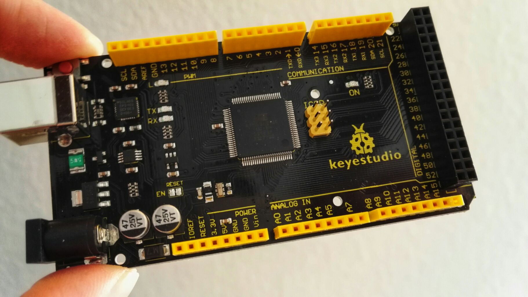
You probably heard about this before: An Arduino can be made into an excellent DIY joystick. Most examples use a Leonardo or Micro for this for a very good reason. They one comes basically with a chip that is recognized as HID (Human Interface Device) hardware on any modern operating system.
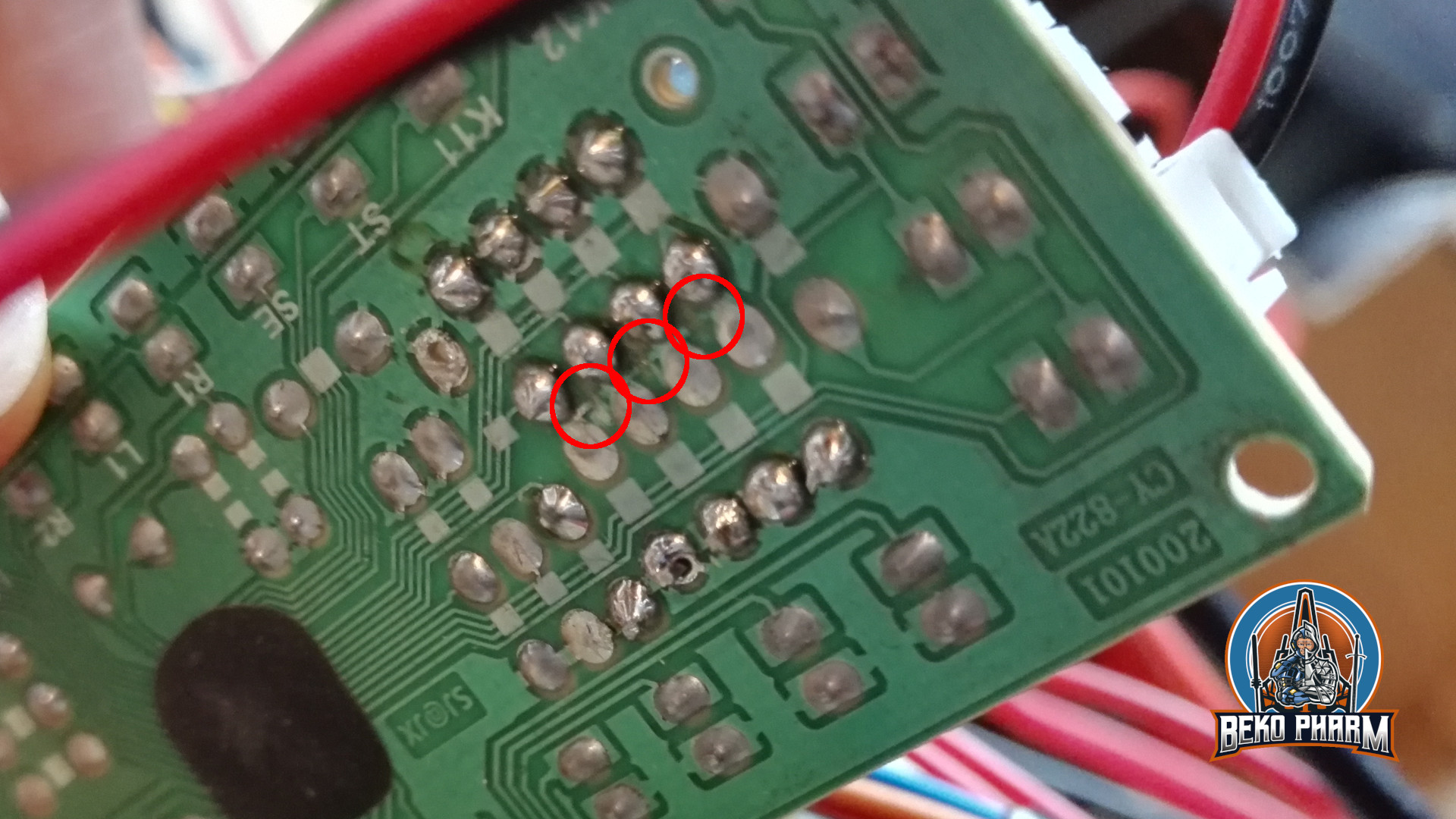
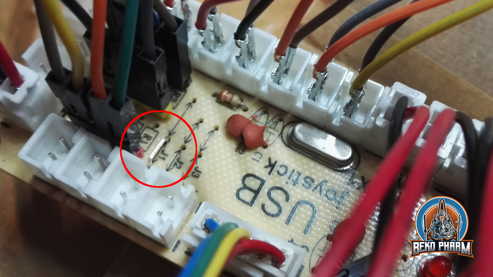
This is not the case with a Mega. This one has other perks but HID it is not. It sure shows up as USB device and a ttyUSB is raised where serial communications with the Arduino can be initiated. I’m also aware that some flash the built in programmer of the Mega so it starts operating like the others (which obviously removed the built in programmer). I’m on Linux PC though so I thought it’s basically a job of tricking the system into recognizing it as joystick and call it a day and OMG was I wrong!
How it’s not done
My train of thoughts was like this: Linux still supports plenty of old serial joysticks so how complicated can it be to send some bits an existing driver recognizes. Old hardware like this is usually glued to the driver with the tool inputattach of the Linux Console Project. This does basically initialise a joystick on some serial connection and sends it off to a fitting kernel driver. This way even non-USB, or let’s better say non-HID hardware, is mapped to a kernel driver who in return will set-up the joystick subsystem and manage the communication with the stick via a serial connection.
Turns out I’m not the first one with that idea and apparently someone made it work by connecting old Playstation Controller and a Wii Classic Controller to an Ardunio and fake a Stinger device without the use of HID so Kudos to Jarno Lehtinen here and his Linux-Arduino-Serial-Joystick repo – you sure did sent me down a rabbit hole of horror and amazement. I couldn’t even get inputattach to wait for that magic string to be sent with anything else than 9600 baud and aligned stars! I also had to throw socat into this horrible mix because the Arduino would insist on rebooting on init so a timeout was guaranteed! In case you wonder how I did this:
socat -r left.raw -R right.raw pipe:/dev/ttyUSB0 PTY,link=/dev/ttyUSB1,rawer
# and xdd to show me the debug juice
tail -f left.raw | xxd -c4
# and on yet another terminal
inputattach --baud 9600 --stinger /dev/ttyUSB1
This also meant that I had to tear everything down for reprogramming the Arduino. Anyway, in the end I could finally get through that init phase where the stinger related code in inputattach is waiting for the magic key after sending “ E5E5” to finally load the Stinger kernel driver – communication for both ways confirmed!
    // "\r\n0600520058C272";
    byte byteResponse[] = {0x0D, 0x0A, 0x30, 0x36, 0x30, 0x30, 0x35, 0x32, 0x30, 0x30, 0x35, 0x38, 0x43, 0x32, 0x37, 0x32};
    if (Serial.availableForWrite() >= sizeof(byteResponse))
    {
      Serial.write(byteResponse, sizeof(byteResponse));
    }
At this point I had a pipe to prevent the timeout due to the resetting Arduino, the _only_ working baud rate 9600 I could figure out with the Mega, a loaded driver that was recognized as joystick and was sitting put and did… absolutely nothing. Null. Nada. Not a single bit made it to the driver and I could not figure out why. My guess is it needs a change in the baud rate to the original 1200 (?) of the Stinger but I have no idea if this is true. I could also not find any way how the stream is controlled and since the driver would fill up 2 bytes all the time and interpret them there is a fair chance that it would simply be one byte off all the time. Speculations tho, I simply didn’t grasp the stinger.c source so this is all just a theory. I do not want to admit how much time I sunk into this and I was pretty frustrated at this point. Reading some stupid serial? Not like this! Too many hoops!
So I threw it all in the bin 🚮
How it’s probably done
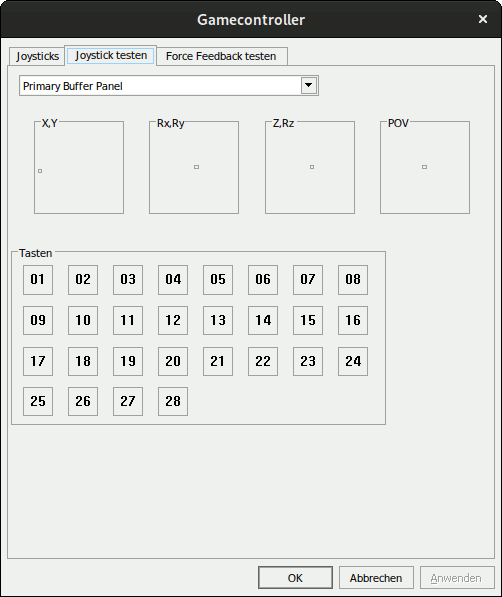
Say hi to /dev/uinput where you can basically raise virtual devices, like a joystick, without [much?] pain. I’m not the first one, of course, and funny enough the reason behind is very similar to mine. Read more on Virtual joystick on Linux by Gwilym Kuiper where this is all explained in great detail. The referred code at https://github.com/gwilymk/arduino-joystick sure did help me to get started and even without having touched Rust ever before I was able to quickly adjust this for my needs, doubling the possible buttons and get it up and running in just a few hours for my Linux PC. Cheers mate (also Jarno Lehtinen – you teached me a lot that day :D) 🕹️
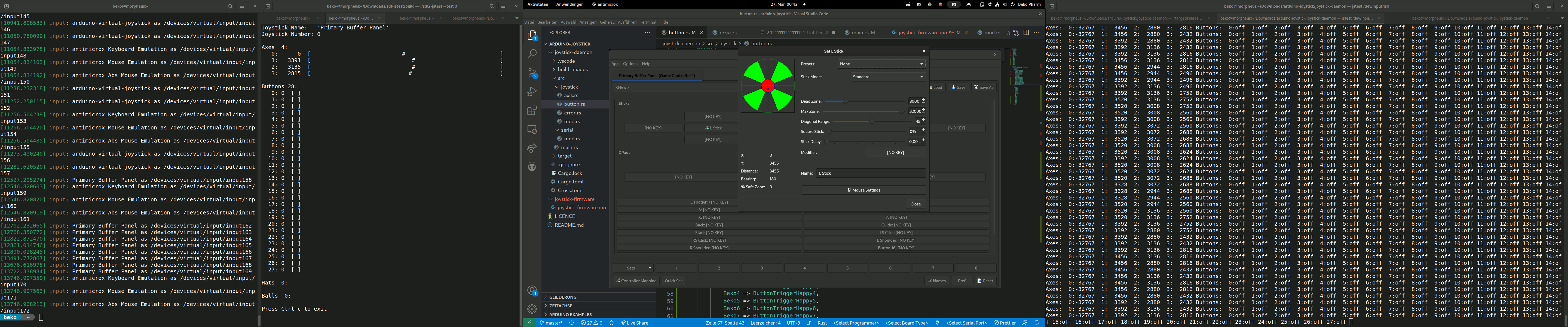
So here it is: A Mega acting as joystick without HID over a serial connection driven by a userspace daemon (means no kernel driver required) written in Rust providing a virtual uinput device for a joystick on the “modern” event system. Heck it’s even recognized in Wine!
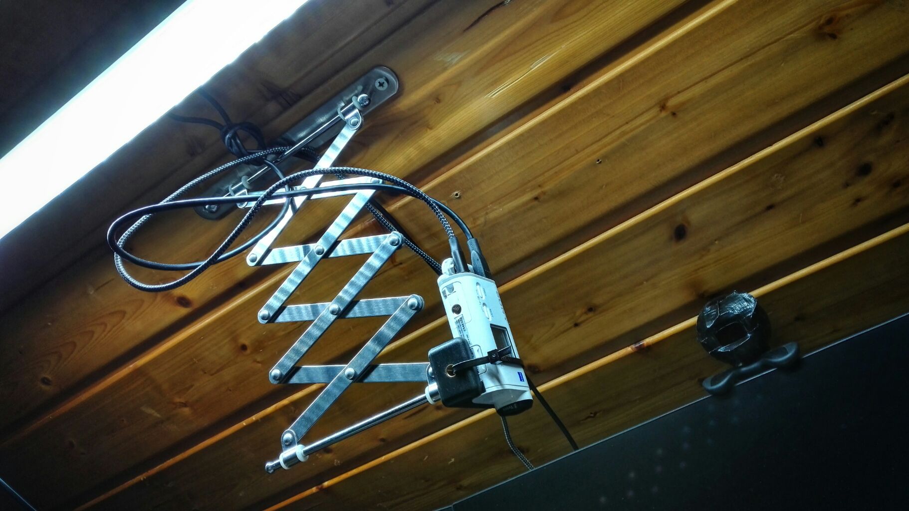
What a journey to begin with. Now I need a back-channel for my blinky lights so I get my Raspberry Pi back from simpit duty 🙃