Okay, recap from the last making session of the button box for my #simPit. What I achieved this time: The LCD controller has now a place inside the contraption while the LCD controller buttons are screwed on the outside. This is mostly because I have no buttons laying around to be used instead. I did note down the pin-out of the connector though so I can change this any time. It has a funny LED though that has 3 pins, GND, Red and Green. Uncertain what to make of this.
The button box itself was put on stilts for the extra room required. The LCD itself is prepared to be added to the button box but I’ve to remove part of the former hinges because they are way too sturdy to be removed with a simple cutter knife. I’ll probably need a grinder or a saw and that’s work I will not do at my computer but in the basement.
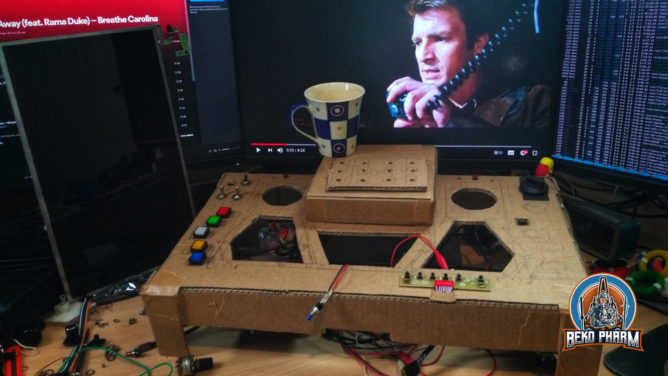
Next was preparing the ICP in the centre. For this I created a new box of cardboard that is attached to the button box with tape that also acts as a hinge so I can “open” it to work on the switches that go there. I also noticed that my knobs for the rotary encoders or potentiometer are way too big. I could compensate this with more height but I don’t want the ICP to dwarf the button box itself 🤔 So… mebbe I’ll use smaller knobs. On the topic of knobs: Dem, the costs for decent sized knobs are insane. Like ~8 EUR for one knob! So… perhaps I’ll go for spray painted wood here. I don’t know yet 🤷
Yeah, and I got tired of calling it just “button box”. It’s not. It’s a “glorified button box mock-up with a gorram LCD made from cardboard”. So I decided that it needs a name and as a nerd I came up with… Primary Buffer Panel! Firefly fans will know. Others may educate themselves via https://www.youtube.com/watch?v=mY59BYSrxn0 and have a laugh.
It’s also a running gag in the family. My van tended to loose all kind of parts while driving and when Serenity aired my dad yelled at this very specific scene: “Hah, just like your car!” 🤣

@bekopharm#BringBackFirefly
bringbackfirefly
@tpheine So say we all 😜
@tpheine btw the Black Ocean books have the same vibes. In fact the author wrote them just because of this.
@bekopharmAll 4 Mission Books on my wishlist. Thanks!
@tpheine enjoy some new bands of misfits 🙂