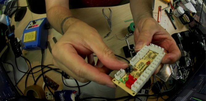
This is a brief description how to mod an CY-822A USB joystick controller into accepting analogue input. I’ve done this modification now with two of my PCBs and worked with both for an extended period of time without any problems. To achieve this two things have to be done – at your own risk!
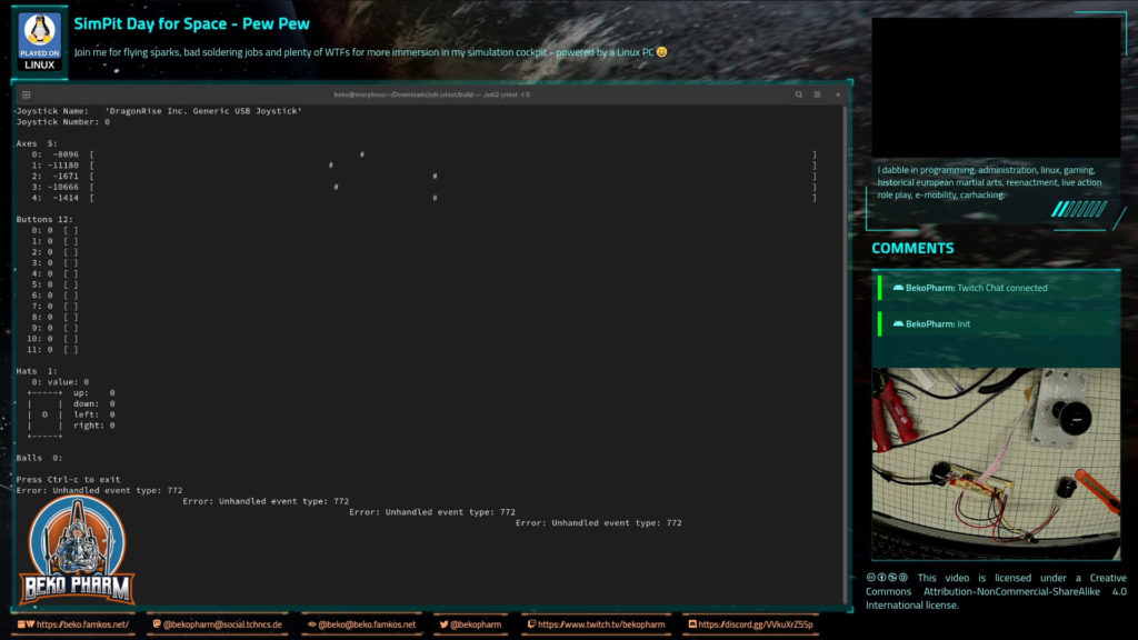
The PCB comes with 5 analogue axes according to my Linux PC and sdl2-jstest and while I’m not sure where the 5th is located a tiny modification will allow us to use at least 4 of the axes.
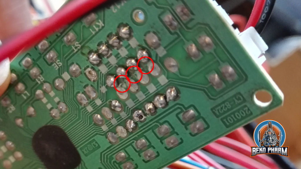
Locate the resistors R1 – R8 on the front that make up for 4 possible connections for analogue input with the use of potentiometers. There are 2 resistors with ~10k on the PCB that have to go. The 2 resistors hold 4 of the 5 axes perfectly still in the centre because the middle lane is bridged on the backside. This is the part where the conductor path has to be interrupted. Locate the central lane and simply scratch off the track with a sharp knife. Also clean all the holes of R1 to R8 so you can solder in some new pins for easier access. Use a multimeter to make sure that none of the 4 central soldering points are connected with each other any more. The upper and lower ones stay connected (Plus and GND).
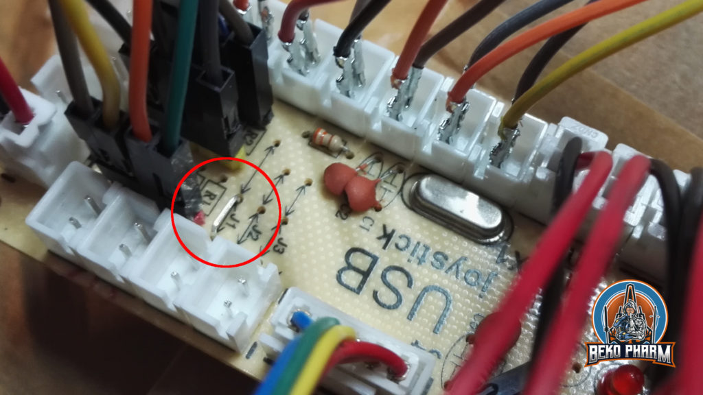
Next we want to remove the zero ohm resistor at J1 and add a wire bridge instead. Look for an resistor with a single black ring next to R2, remove it, and solder in the wire bridge next to R1. This is basically a jumper setting but with a bridge. I’ve no idea why the designer went with a zero ohm resistor and not with a bridge. My only guess is that this was cheaper for the assembly machines.
Anyway, this will make the board boot in analogue mode so we do not have to use a mode switch on power on every time. This serves two purposes: Axes are now read from input and actually send as joystick events on the USB wire while the former digital joystick connector (5 pins) is now mapped to Up/Down/Left/Right buttons – so no extra buttons are needed here any more (but can still be added, of course).
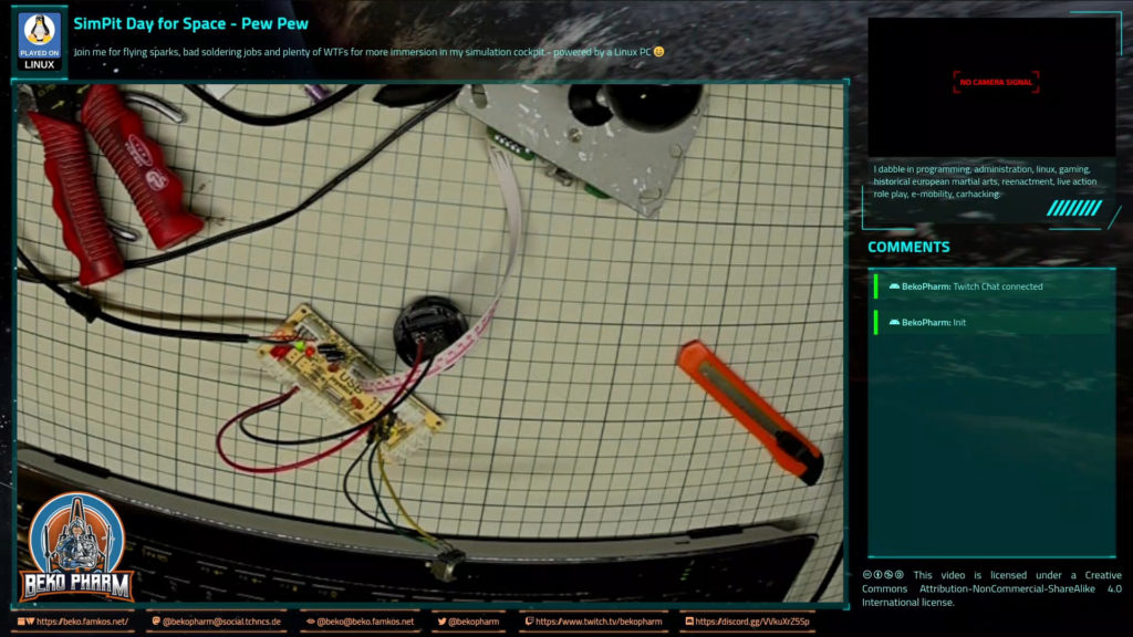
Now it’s time to connect potentiometers as analogue inputs. This is pretty straight forward. Just make sure that the central connector goes to the centre of each axes. Change the upper with the lower pin if the direction is not as desired.
Please note that any axes that has no input attached will report _a lot_ of jitter making your game/app go nuts. This is what the former resistors at R1 and R2 were there for.



Reposts
Likes